Fig. 2, Fig. 1, Page 2 – Whelen HA238C User Manual
Page 2: Cable (deutsch/deutsch) cable (amp/deutsch), Amp deutsch
Page 2
1.
1
S30HA Flash Tube, Red
01-0461403-R_
01-0461403-0_
01-0461403-B_
01-0461403-A_
1
S30HA Flash Tube, Amber
S30HA Flash Tube, Blue
S30HA Flash Tube, Clear
1
1
2.
3.
2
1
#6 x ½” Phillips Plasti-Screw
Foam Gasket
15-065419-080
38-0241407-00
01-0461403-V_
01-0461403-G_
S30HA Flash Tube, Green
S30HA Flash Tube, Violet
1
1
-
Cable (Amp/Amp)
01-0440624-_ _
4.
5.
6.
-
-
Cable (Deutsch/Deutsch)
Cable (Amp/Deutsch)
Cable Length
Part Number Key
05 = 5’
10 = 10’
15 = 15’
20 = 20’
25 = 25’
30 = 30’
01-0442995-_ _
01-0442199-_ _
Item
Description
Qty.
Part No.
0 = Amp Connector
1 = Deutsch® Connector
1
1
2
1
1
1
1
1
2
2
2
Mounting
Surface
Mounting
Hole
2
1
3
Amp
Deutsch®
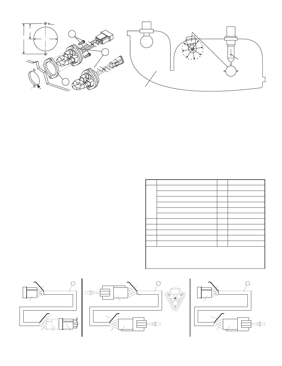
Top view of a “composite”
Headlight or Taillight housing.
Focal point of
the reflector
is the filament
location of
the lamp.
Insert the Strobe Light from the back
or bottom of the headlight or rear
stoplight housing, as close to the
focal point as possible.
WARNING! When selecting
a mounting location, be sure
that no part of the housing
or any other component is
located within a 1" radius
'clearance bubble' around
the strobe tube.
FIG. 2.
Mounting Hole
1.282"
FIG. 1
0.105” DIA.
holes for
mounting
screws.
1” DIA.
0.641”
Once all the pins are
installed, insert wedge
into the pin housing
with the arrow on the
wedge pointing to the
top (as shown).
Shield Wire (see
cable information).
Shield Wire (see
cable information).
Shield Wire (see
cable information).
FIG. 3
Insert wires with sockets:
wire - POS. 1
wire - POS. 2
wire - POS. 3
RED
BLACK
WHITE
Insert wires with sockets:
wire - POS. 1
wire - POS. 2
wire - POS. 3
RED
BLACK
WHITE
Insert wires with sockets:
wire - POS. A
wire - POS. B
wire - POS. C
RED
BLACK
WHITE
Cut shield wire flush
with cable jacket.
Cut shield wire
flush with
cable jacket.
Cut shield wire
flush with
cable jacket.
3-Position
Socket Housing.
3-Position
Socket Housing.
3-Position
Socket Housing.
From Strobe Light
Head Assembly.
12
3
32
1
Insert wires with pins:
wire - POS. 1
wire - POS. 2
wire - POS. 3
RED
BLACK
WHITE
Insert wires with pins:
wire - POS. 1
wire - POS. 2
wire - POS. 3
RED
BLACK
WHITE
Insert wires with pins:
wire - POS. A
wire - POS. B
wire - POS. C
RED
BLACK
WHITE
3-Position Pin Housing
to Strobe Power Supply.
3-Position Pin Housing
to Strobe Power Supply.
3-Position Pin Housing
to Strobe Power Supply.
3 CONDUCTOR POWER
CABLE (OPTIONAL)
3 CONDUCTOR POWER
CABLE (OPTIONAL)
3 CONDUCTOR POWER
CABLE (OPTIONAL)
4
6
5
32
1
32
1
A
B
C
Wedge
A
C
B
Wedge
A
C
B
Wedge
A
C
B
INSTALLING A STROBE LIGHT INTO A COMPOSITE HEADLIGHT OR
TAILLIGHT ASSEMBLY:
1.
Select the mounting location for the strobe light head, keeping in mind the
following:
•
The strobe light will share the same reflector as the headlight, brake
light, or signal light. Make sure that the strobe light does not
interfere with the proper operation of these lights.
•
No part of the housing or any other component can be within a 1"
radius ‘clearance bubble' around the strobe tube (Fig. 2).
•
The strobe light must not be installed above the horizontal
centerline of the reflector.
•
The strobe light must not be installed above any OEM-supplied light.
2.
Remove the reflector assembly from the vehicle. Choose a surface in the
rear or bottom of the housing which is as flat as possible. Using a 1” hole
saw, cut a clearance hole for the strobe light in the housing as shown in
Figure 1. Using the strobe light head assembly as a template, mark the
location of the two holes for the two mounting screws.
WARNING: High Voltage on glass tube. This strobe lamp unit is an open
flash tube with no protective lens. Proper installation is required. Do not
touch the strobe tube assembly while in operation.
CABLE INFORMATION
On each end of the optional 3-conductor power cable is a shield wire. Cut this
wire on the end connected to the strobe lighthead assembly flush with the cable
jacket. The shield wire on the cable end to be connected to the strobe power
supply is to be grounded to the vehicle chassis when the radio or other
communication system interference is a problem. If this shield wire is not
grounded, cut it flush with cable jacket. KEEP THIS WIRE AS SHORT AS
POSSIBLE WHEN GROUNDING.
NOTE: For radio frequency interference protection, it is advisable to
ground the shield wire on the power supply end.
NOTE: Whelen strobe light systems are designed to interface with the
Whelen UPS strobe light power supply. Detailed wiring, switching and
installation instructions are enclosed with the UPS unit.
WARNING: When inserting the wire terminals into the cable connectors,
be sure that the correct wire color is inserted into its designated position
(see Fig. 3)
WARNING: The strobe light power supply is a high voltage device. Do not
remove strobe tubes or dismantle strobe light head assembly while in
operation. WAIT 10 MINUTES after turning off power before starting work
or any trouble shooting.
WARNING: All customer supplied wires that connect to the positive (+)
terminal of the battery must be sized to supply at least 125% of the maxi-
mum operating current and fused “at the battery” to carry the load!
WARNING! Automotive composite housings use low-temp plastic in their
construction. The use of strobe power supplies in excess of 10 watts per
outlet, may cause the housings to melt.
Modification of your vehicle’s reflector housings may void your vehicle
warranty. Check with dealer/supplier before installation.