Whelen CL25C User Manual
Whelen For the car
For warranty information regarding this product, visit
www.whelen.com/warranty
©2000 Whelen Engineering Company Inc.
Form No. 13527A (112707)
®
ENGINEERING COMPANY INC.
Route 145, Winthrop Road,
Chester, Connecticut 06412
Phone: (860) 526-9504
Fax: (860) 526-4078
Sales Email:[email protected]
Canadian Sales:[email protected]
Customer Service:[email protected]
www.
.com
56-series 12-Volt Compartment Light
Safety First
This document provides all the necessary information to allow your Whelen product to be properly and safely installed. Before beginning the installation
and/or operation of your new product, the installation technician and operator must read this manual completely. Important information is contained
herein that could prevent serious injury or damage.
Installation...
CAUTION! Mounting this light will require drilling into its mounting surface. It is
absolutely necessary to make sure that no other vehicle components could be
damaged in the process. Check both sides of the mounting surface before starting.
If damage is likely, select a different mounting location.
1. Position the base reflector onto its proposed mounting surface. Locate the 3 mounting
holes shown.
2. Using an awl or other suitable tool, scribe the surface where the mounting hole are to
be drilled. Use the base as a guide.
3. Carefully drill the mounting holes in the areas scribed in step 2. The size of the drill bit
should be determined by the size of the mounting hardware (#6 x 3/4” PPHSMS) and
the thickness of the mounting surface.
4. After the mounting holes have been drilled, position the mounting gasket onto the
mounting surface. Insert the mounting screws through the holes in this gasket and into
the mounting surface to hold the gasket in place.
5. Locate the wire passage hole in the gasket. Scribe a mark on the mounting surface at
the location of this hole. Remove the gasket from the mounting surface.
!
!
!
!
!
Proper installation of this product requires the installer to have a good
understanding of automotive electronics, systems and procedures.
If mounting this product requires drilling holes, the installer MUST be sure that
no vehicle components or other vital parts could be damaged by the drilling
process. Check both sides of the mounting surface before drilling begins. Also
de-burr any holes and remove any metal shards or remnants. Install grommets
into all wire passage holes.
Do not install this product or route any wires in the deployment area of your air
bag. Equipment mounted or located in the air bag deployment area will damage
or reduce the effectiveness of the air bag, or become a projectile that could
cause serious personal injury or death. Refer to your vehicle owners manual for
the air bag deployment area. The User/Installer assumes full responsibility to
determine proper mounting location, based on providing ultimate safety to all
passengers inside the vehicle.
For this product to operate at optimum efficiency, a good electrical connection to
chassis ground must be made. The recommended procedure requires the
product ground wire to be connected directly to the NEGATIVE (-) battery post.
If this product uses a remote device to activate or control this product, make sure
that this control is located in an area that allows both the vehicle and the control
to be operated safely in any driving condition.
!
!
!
!
!
Do not attempt to activate or control this device in a hazardous driving situation.
This product contains either strobe light(s), halogen light(s), high-intensity
LEDs or a combination of these lights. Do not stare directly into these lights.
Momentary blindness and/or eye damage could result.
Use only soap and water to clean the outer lens. Use of other chemicals could
result in premature lens cracking (crazing) and discoloration. Lenses in this
condition have significantly reduced effectiveness and should be replaced
immediately. Inspect and operate this product regularly to confirm its proper
operation and mounting condition. Do not use a pressure washer to clean this
product.
FAILURE TO FOLLOW THESE PRECAUTIONS AND INSTRUCTIONS COULD
RESULT IN DAMAGE TO THE PRODUCT OR VEHICLE AND/OR SERIOUS INJURY
TO YOUAND YOUR PASSENGERS!
WARNING! All customer supplied wires that connect to the positive (+) terminal
of the battery must be sized to supply at least 125% of the maximum operating
current and
“at the battery” to carry that load. DO NOT USE CIRCUIT
BREAKERS WITH THIS PRODUCT!
FUSED
6. Using a 3/8” (.375”) drill bit, drill a wire passage hole into the mounting surface at the
area scribed in step 5.After drilling, de-burr and grommet (customer supplied) this hole.
7. Route the RED and BLACK lamp wires through the wire passage hole in the mounting
gasket. Using appropriately sized wires, extend the RED lamp wire to a switched,
+12VDC power source capable of accommodating an additional 2 Amp load. Extend
the BLACK wire to chassis ground.
8. Feed all excess wire through the cable access hole away from the lamp base. Do not
allow any wires between the surface and gasket. Test the lamp for proper operation
before proceeding.
9. Position the mounting gasket and lamp base onto the mounting surface. Secure the
base to the surface using the provided hardware. Mount the lens onto the base and
secure using the #10 x 5/8” PPHSMS.
All customer supplied wires, that connect to the positive terminal of the battery,
must be sized to supply at least 125% of the maximum operating current, & fused at
the battery to carry the load.
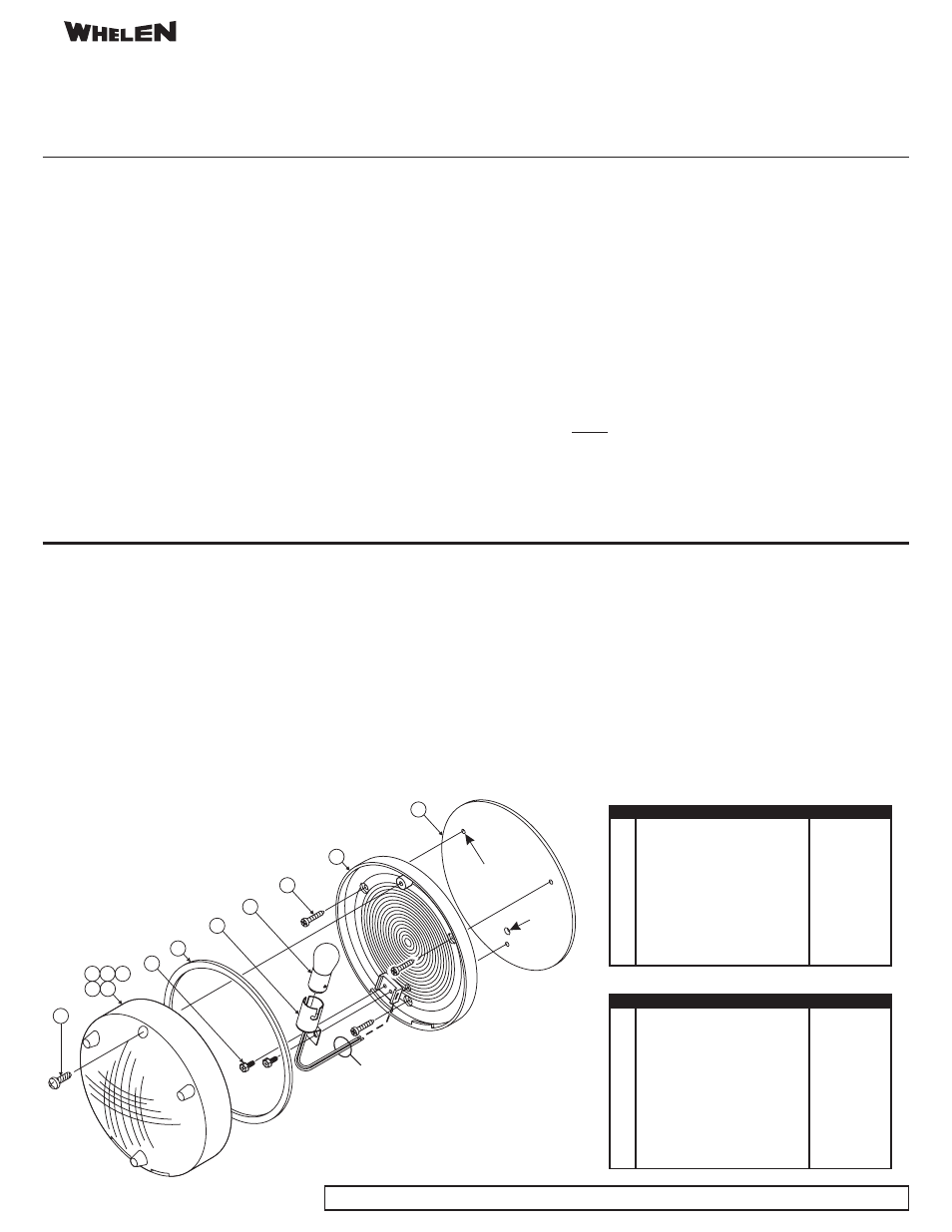
1
#10 x 5/8” PPH Sheet Metal Screw
--------------------
2
Lens, Red
68-1181783-R0
3
Lens, Green
68-1181783-G0
4
Lens, Blue
68-1181783-B0
5
Lens, Amber
68-1181783-A0
6
Lens, Clear
68-1181783-C0
7
#6 x 5/16” Hex Washer Head Screw
--------------------
8
Lens Gasket
38-0261637-00
9
Bulb Holder
33-05621560-0
1
Bulb 23 Watt (1076)
--------------------
11
#6 x 3/4” PPH Sheet Metal Screw
--------------------
12
Base Reflector
68-5981901-01
13
Mounting Gasket
38-0261657-00
0
,
Description
Item
Part Number
1
#10 x 5/8” PPH Sheet Metal Screw
--------------------
2
Lens,
Red
68-11
-R0
3
Lens,
68-11
-G0
4
Lens,
68-11
-B0
5
Lens,
68-11
-A0
6
Lens,
68-11
-C0
7
#6 x 5/16” Hex Washer Head Screw
--------------------
8
Lens Gasket
38-0261637-00
9
Bulb Holder
33-05621560-0
1
Bulb 23 Watt (1076)
--------------------
11
#6 x 3/4” PPH Sheet Metal Screw
--------------------
12
Base Reflector
68-5981901-01
13
Mounting Gasket
38-0261657-00
On/Off Switch (not shown)
41-0101010-00
Optic Directional,
w/Hole
63244
0
,
Optic Directional, Green w/Hole
63244
Optic Directional, Blue w/Hole
63244
Optic Directional, Amber w/Hole
63244
Optic Directional, Clear w/Hole
63244
Description
Item
Part Number
5
2
6
3 4
8
9
Wire
Passage
Hole
Mounting
Hole
11
12
13
1
10
7
RED - +12VDC (Fuse@3A)
BLACK - Chassis Ground
56-series Compartment Light
56-series Compartment Light w/Switch (not shown)