Mounting clip location chart, Installation – Whelen Fluorent & Fluorent Plus Series User Manual
Page 2
Page 2
Stop
brackets
should
fit
snugly
to
both
endcaps
peel
off
backing
MOUNTING
SURF
ACE
#6 X 5/8"
PPH PLASTI-LOC
CAUTION! DO NOT LOOK DIRECTLY AT THESE LED’S WHILE THEY ARE ON.
MOMENTARY BLINDNESS AND/OR EYE DAMAGE COULD RESULT!
I M P O R TA N T W A R N I N G !
1.5
1.5
1.5
1.5
1.5
1.5
1.5
1.5
1.5
1.5
1.5
1.5
1.5
1.5
1.5
1.5
1.5
1.5
1.5
1.5
1.5
1.5
12
16.5
16.5
21
21
17
17.25
17.25
17.25
17.25
20
19.5
19.5
19.5
19.5
21.75
21.75
21.75
21.75
20
20
17
17
12
12
9
18
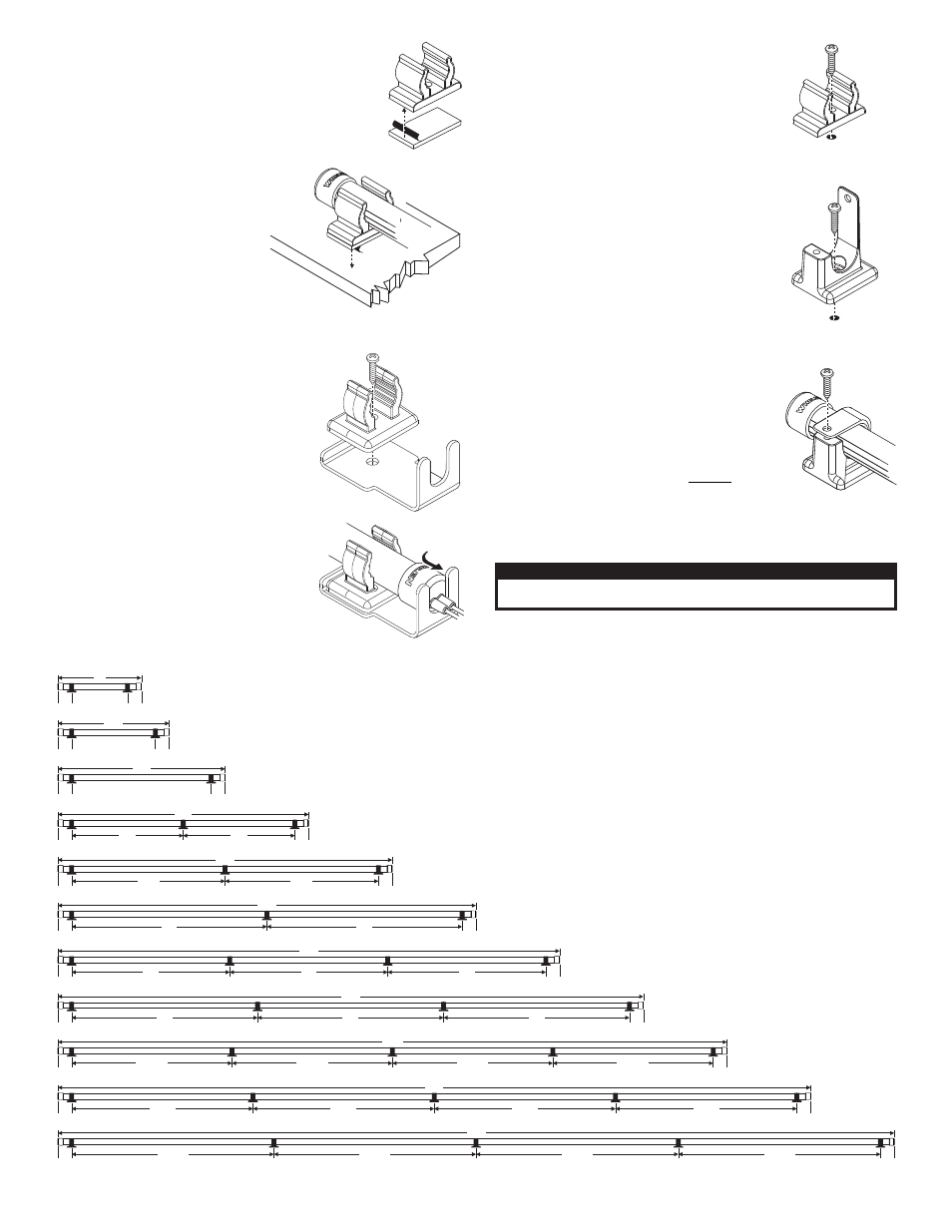
Mounting Clip Location Chart
As shown, all Fluorent-series lights require the use of a minimum
of two (2) mounting clips, each positioned so that the centerline
of the clip is 1.5 inches inboard from the outside end of the Fluorent
tube. Fluorent models having a length of 27 inches or more require
supplemental clips positioned along the tube. Refer to this chart
f o r
t h e
p r o p e r
p o s i t i o n
o f
t h e s e
s u p p l e m e n t a l
c l i p s .
Note: All measurements shown are in Inches.
27
36
45
54
63
72
81
90
Installation:
1.
Tape Mounting: Peel the backing off on one side of
the tape and install the tape onto the mounting clips
by applying firm pressure to the back of the tape.
2.Snap the mounting clips onto the light tube and use the
chart below to determine the amount of clips used and
the space between them.
3.Peel the backing off of the other side of
the tape, place the light into position on
the mounting surface and apply
firm pressure to the clips to secure
them.
WARNING: Apply pressure to only
the clips and not the light tube which
might break the tube.
(Proceed to step 6 of permanent mounting)
CAUTION: Permanent mounting of this
product will require drilling. It is
absolutely necessary to make sure that
no other vehicle components could be
damaged by this process. Check both
sides of the mounting surface before
starting. If damage is likely, select a
different mounting location.
1. Permanent Mounting: Secure the
supplied mounting clips onto the light
tube. Use the chart below to determine the
amount of clips used and the space
between them. NOTE: Permanent
mounting requires a stop bracket at
both ends of the light tube. While
determining the position of the
mounting clamps on the ends of the
tube, be sure to allow for both stop
brackets to fit snugly to both end caps.
open
clip style
8 X 1/2"
PPHSMS
closed
clip style
8 X 1/2"
PPHSMS
2.Place the light onto the mounting location and
mark the location of the mounting holes onto the
mounting surface.
3.Remove the light and drill the mounting holes in
the locations marked in step 2 with a #24 drill.
4.Install the mounting clips onto the mounting
surface using the supplied #8 X 1/2” PPHSMS.
Add a stop bracket at each end of the light.
5.For the locking clips, place the light into the clip,
pull the strap over and secure the light with the
supplied screws. For the open clips, just snap the
light into the clip.
6.Extend the WHITE wire to the positive terminal of
the battery. Install a (user supplied) fuse block on
the WHITE wire near the power source and
install a 1 amp fuse into the fuse block. Extend
the BLACK wire to the ground terminal of the
battery. (See wiring diagram below.)
WARNING: All customer supplied wires that
connect to the positive terminal of the battery
must be sized to supply at least 125% of the
maximum operating current and FUSED at the
battery to carry that load. DO NOT USE
CIRCUIT BREAKERS WITH THIS PRODUCT!
peel
off
backing