Fig. 1, Fig. 2, Fig. 5 – Whelen MBCC11JJ User Manual
Page 2
Page 2
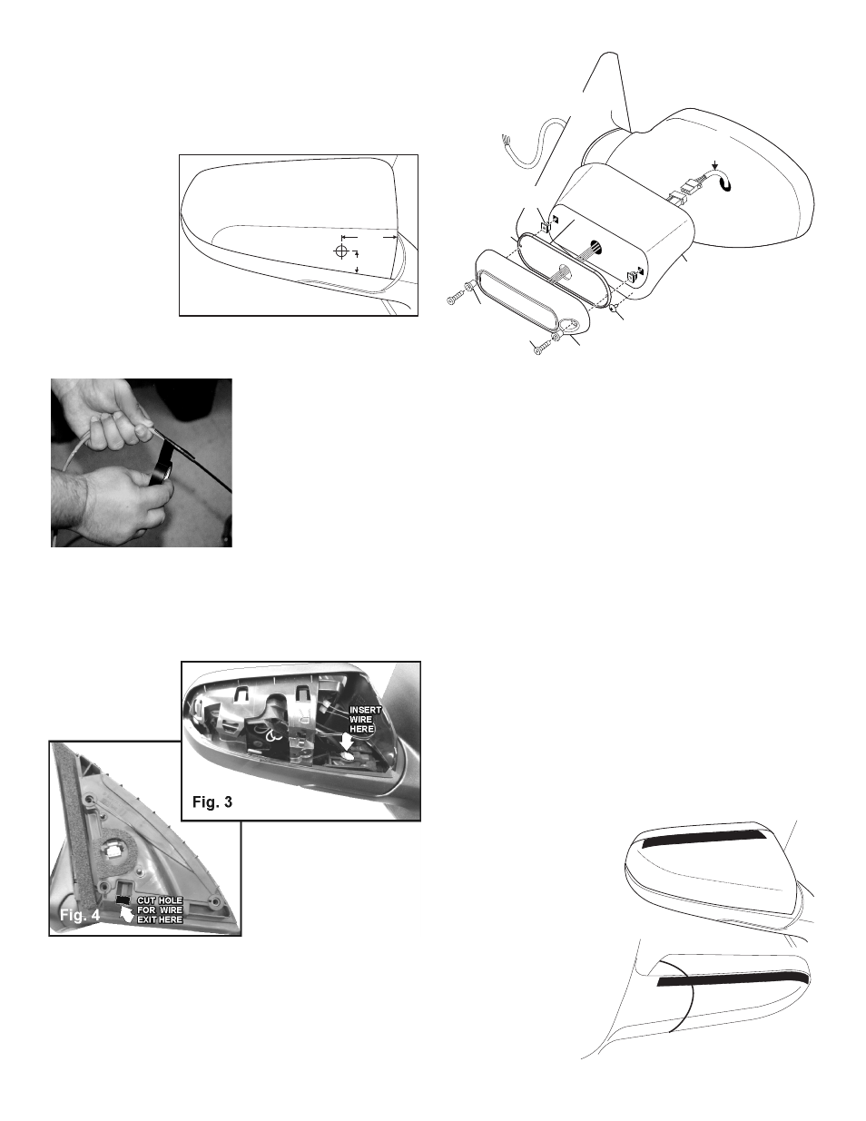
Mirror Assembly Cover
Fig. 1
1”
2 1/2”
Drill 3/4 Inch
Wire Hole
Remove the Side Mirror Assemblies:
To install this product, you must remove both side mirror assemblies
from the vehicle. Following manufacturers instructions Unplug the
mirror assembly harnesses and remove both mirror assemblies.
Preparing Mirror Assembly:
1.
Remove the mirror
assembly cover
and mark off the
wire hole location
onto the front of
the mirror
assembly cover
measuring 2 1/2”
from the inboard
edge of the cover
and 1” from the
bottom edge of
the cover. Drill the
wire hole using a half inch drill bit (Fig. 1).
Preparing the Mirror-Beam™ cable:
Because the Mirror-Beam™ cable
must be routed through a
specific, narrow and twisting path
within the mirror assembly, it will
be necessary to temporarily
extend the length of the cable.
1.
Locate the ty-wrap (included)
and cut the fastener-end off.
2.
Locate the end of the cable
that has PIN-type terminals
installed on the wires. Cut off
the non-insulated wire (not
used).
3.
Strongly secure the ty-wrap to the cable with electrical or similar tape.
It is important to have a sufficient length of the ty-wrap secured to the
cable (2” minimum) (Fig. 2).
Routing the Mirror-Beam™ Cable:
1.
Insert the ty-wrap
into the front of the
mirror assembly
and rout the
Mirror-Beam™
cable into the front of the
mirror assembly where the
assembly harness enters
and exiting out the base.
You will need to cut a hole in
the base as shown, for the
cable to exit. There should
not be more than 4 - 5” of
cable exiting the front of the mirror assembly (Figs 3 & 4).
2.
Insert the end of the cable into the hole previously drilled into the
mirror assembly cover. Now snap the cover back onto the mirror
assembly.
3.
Remove the ty-wrap from the cable. Install the socket connector
(supplied) onto the end of the cable coming out of the front of the
mirror assembly (Fig. 5). (see wiring diagram).
Affixing Mirror-Beam™ Housing to Mirror Assembly:
1.
Remount the mirror assembly onto the vehicle using the original
hardware and reconnect the mirror power cable. Route the Mirror-
Beam™ cable through the door, along the same path as the vehicle’s
main power harness. Make sure that neither of the harness cables
are crimped or pinched. Tighten all nuts firmly, reattach the panel
covering the mirror assembly base and re-secure the door panel.
2.
Mount the lighthead to the Mirror-Beam™ housing and plug the
lighthead into the connector coming from the front of the mirror
assembly. This connection will be tucked between the Mirror-Beam™
housing and the mirror assembly (Fig. 5).
3.
NOTE: The following procedure requires that the mirror
assembly be no colder than 60°F (18°C). Thoroughly clean the
plastic mirror assembly and the inside surface of the Mirror-Beam™
housing using a 50/50 mixture of isopropyl (not rubbing) alcohol and
water. Dry completely.
4.
Locate the two, 6” strips of double-sided adhesive tape (included).
Peel the protective strip from one side of one piece of tape and
mount it onto the top of the mirror assembly curving around the
outboard side. When properly positioned, the tape will go along the
rear (mirror side) edge of the mirror assembly cover. After the tape is
mounted, it is important to apply pressure to the protective backing
so that the tape adheres to the surface (Fig. 3).
5.
Peel the protective strip from the other piece of tape. Using the
procedure outlined in the previous step, adhere it along the bottom of
the mirror assembly cover along the seam.
6.
Hold the Mirror-Beam™ housing in position on the mirror assembly
and trim and remove any exposed tape. Remove the housing and
fold the protective backing strips of the tape so that 1/2” to 3/4” of
backing is extended
over the edge of the
mirror assembly.
7.
Mount the Mirror-
Beam™ housing
onto the mirror
assembly.
The
housing must fully
engage the mirror
assembly. Press
the housing firmly
onto the exposed
tape on the mirror
assembly.
Fig. 2
TAPE
TOP
BOTTOM
TAPE
#8 X 1/2" PHILLIPS
TRUSS SCREW
GASKET
Mirror-Beam™
HOUSING
NOTE: MIRROR ASSEMBLY SHOWN
FOR REFERENCE ONLY!
#8 SCREW
GROMMET
LIGHTHEAD
#6 X 1
PPHSMS
BUSHING
Cable
exits mirror
assembly
base here
4 to 5
i n c h e s
of cable
Fig. 5
- MBFT11AA MBFT11JJ MBFF12AA MBFF12JJ VMFF12AA RSA02ZCR RSA03ZCR RVA03ZCR RSC02ZCR RSC03ZCR RVC03ZCR RSG02ZCR RSG03ZCR IONSMJ IONSMD IONSMM IONSMWJ IONSMWD IONSMWM WIONSMJ WIONSMD WIONSMM WIONSMWJ WIONSMWD WIONSMWM WIONSMCD IONJ IOND IONM IONWJ IONWD IONWM WIONJ WIOND WIONM WIONWJ WIONWD IONA IONWA WIONA WIONWA IONG IONV3A IONV3AW 3SC0CDCR 3SA00FAR 3SBCCDCR 3SRCCDCR 3SR0CDRR IONV1A IONV1AW PAR28DA PAR28DJ UFM8 20C0CDCR 20C0CDCD SFIOND SFIONJ SFIONE SFP1A SFP1G SFP1J SFP1E SFP1D LINZ6K LINZ6J LINZ6D LINZ61 LINZ62 LINZ65 LINZ6A LINZ6A24 LINZ6G IONSMA IONSMWA IONSMCA WIONSMA WIONSMWA WIONSMCA MBFX11AA MBFX11JJ VMFX11AA SK02JJ SK02WJJ SK01AA SK01JJ SK01WAA SK01WJJ