Fig. 5, Fig. 2, Fig. 4 – Whelen MBDC11AA User Manual
Page 2: Preparing mirror assembly, Preparing the wire harness, Routing harness cable, Fig. 3, Fig.1
Page 2
Fig. 5
ION™
LIGHTHEAD
#6 X 1 PPHSMS
#8 X 1/2"
PHILLIPS
T R U S S
S C R E W
#8 SCREW
GROMMET
GASKET
BUSHING
Exits mirror
assembly
base
Mirror-Beam™
HOUSING
Position connectors between Mirror-Beam™ housing and mirror housing
Exits front
of mirror
assembly
3.4" HOLE
5/8"
FROM
SEAM
FROM
EDGE
Fig. 2
2-5/8"
APPROXIMATE LOCATION
OF SNAPS
Fig. 4
Bottom of base (Facing road)
Insert
harness
here
Insert
harness
here
Insert
harness
here
Cut section
of grommet
out here
Pull grommet
out to feed the
harness through
Harness
exits here
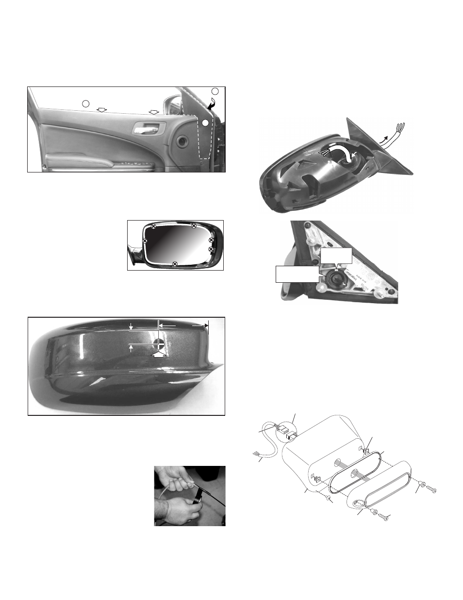
To Remove the Side Mirror Assembly:
1.
Remove the two clips (Fig. 1) from behind the top of the door panel,
which hold the door panel on (A). Carefully pull the door panel out,
just enough so that the panel covering the mirror base can be pulled
away to access the mirror base (B). The panel covering the mirror
base snaps in.
2.
Carefully pull the panel covering mirror base away and remove the
three nuts holding the mirror assembly on, unplug the wiring and
remove the mirror assembly from the vehicle.
Preparing Mirror Assembly:
1.
Remove the cover from the
front of the mirror assembly.
The cover snaps off. Be
careful not to brake the snaps.
The safest method of
removing the cover is to
carefully insert a small
screwdriver around the edge
of the mirror and disengage the snaps (See above).
2.
Measuring from the seam across the top and the inner edge of the
mirror assembly cover, mark off the wire hole location (Fig. 2). Drill
the wire hole through the cover using a 3/4” drill.
Preparing the Wire Harness:
Because the harness cable must be routed through a specific,
narrow and twisting path within the mirror assembly, it may be
necessary to temporarily extend the length of the harness.
1.
Locate the ty-wrap (included) and cut
the fastener-end off.
2.
Locate the end of the harness cable
that has PIN-type terminals installed on
the free wires. Cut off the non-insulated
wire (not used in this application).
3.
Strongly secure the ty-wrap to the
harness cable with electrical or similar
tape. It is important to have a sufficient
length of the ty-wrap secured to the harness (2” minimum) (Fig. 3).
Routing Harness Cable:
First, carefully pull the grommet that holds the mirror power cable,
out of the base so that you will be able to feed the Mirror-Beam™
cable through the wire hole. The power cable wires are attached to
the grommet so be careful not to pull the wires out of their
connection to the mirror.
1.
Insert the ty-wrap into the front of the mirror assembly via the same
pathway as the mirror power cable. Push the ty-wrap through this
opening until the end of the ty-wrap comes out of the mirror base.
Pull the ty-wrap until slack in the harness is gone (Fig. 4).
2.
Pull the harness through the mirror assembly and out the wire exit
hole in the base. There should not be more than 4 - 5” of harness
protruding from the front of the mirror assembly.
3.
Snap the grommet with the mirror power cable back into its hole. You
will have to cut out a small amount of the outside of the grommet to
accommodate the Mirror-Beam™ cable (Fig. 4). Apply a small
amount of RTV sealant around the cable where you cut the grommet.
4.
Insert the end of the harness into the 3/4” hole you drilled in the
mirror assembly cover and snap the cover back onto the mirror
assembly.
5.
Remove the ty-wrap from the harness. Install the socket connector
(supplied) onto the end of the cable coming out of the front of the
mirror assembly (Fig. 5). (see wiring diagram).
Fig. 3
Remove clips from behind door panel
Pull
panel
out
Access
mirror
base
A
B
C
Fig.1