Connecting the mirror-beam™ to power – Whelen MBFX11AA User Manual
Page 3
Page 3
4.
Locate the two, 6” strips of double-sided adhesive tape (included).
Peel the protective strip from one side of one piece of tape and
mount it onto the top
of the mirror
assembly curving
around the outboard
side. When properly
positioned, the tape
will go along the rear
(mirror side) edge of
the mirror assembly
cover. After the tape
is mounted, it is
important to apply
pressure to the
protective backing so
that the tape adheres
to the surface.
5.
Peel the protective
strip from the other piece of tape. Using the procedure outlined in the
previous step, adhere it along the bottom of the mirror assembly
cover.
6.
Hold the Mirror-Beam™ housing in position on the mirror assembly
and trim and remove any exposed tape. Remove the housing and
fold the protective backing strips of the tape so that 1/2” to 3/4” of
backing is extended over the edge of the mirror assembly.
7.
Mount the Mirror-Beam™ housing onto the mirror assembly. The
housing must fully engage the mirror assembly. Press the
housing firmly onto the exposed tape on the mirror assembly.
8.
The remaining protective backing strips must now be removed. The
housing must not be in contact with the backing strips. Starting with
the strip on top, and using a small, flat blade screwdriver gently pry
the housing about 1/4” away from the mirror assembly. Carefully pull
the protective strip “tab” created in step 6, and gently remove it
completely from the tape strip. Do not allow the strip to tear while
being removed.
9.
Repeat for the other tape strip on the bottom.
10. Apply pressure to the Mirror-Beam™ assembly at the tape locations.
Maintain pressure for a minimum of 20 minutes to allow the tape to
properly setup. This can be accomplished by wrapping the Mirror-
Beam™/mirror assembly tightly with adhesive tape.
WARNING: The tape adhesive used in this procedure is fully bonded
after 72 hours @ 70°F (21°C). During this period, do not expose the
Mirror-Beam™ to any unnecessary force, such as the high-pressure
water from a car wash.
WARNING: The outer surfaces of this product may be cleaned with
mild soap and water. Use of any other chemicals may void product
warranty. Do not use a pressure washer.
11. Locate the factory-drilled hole in the Mirror-Beam™ housing. Using a
.125” drill bit and the housing as a template, drill a hole into the mirror
assembly. Using the #8 x 1/2” black oxide phillips truss screw,
(included) secure the Mirror-Beam™ housing to the mirror assembly.
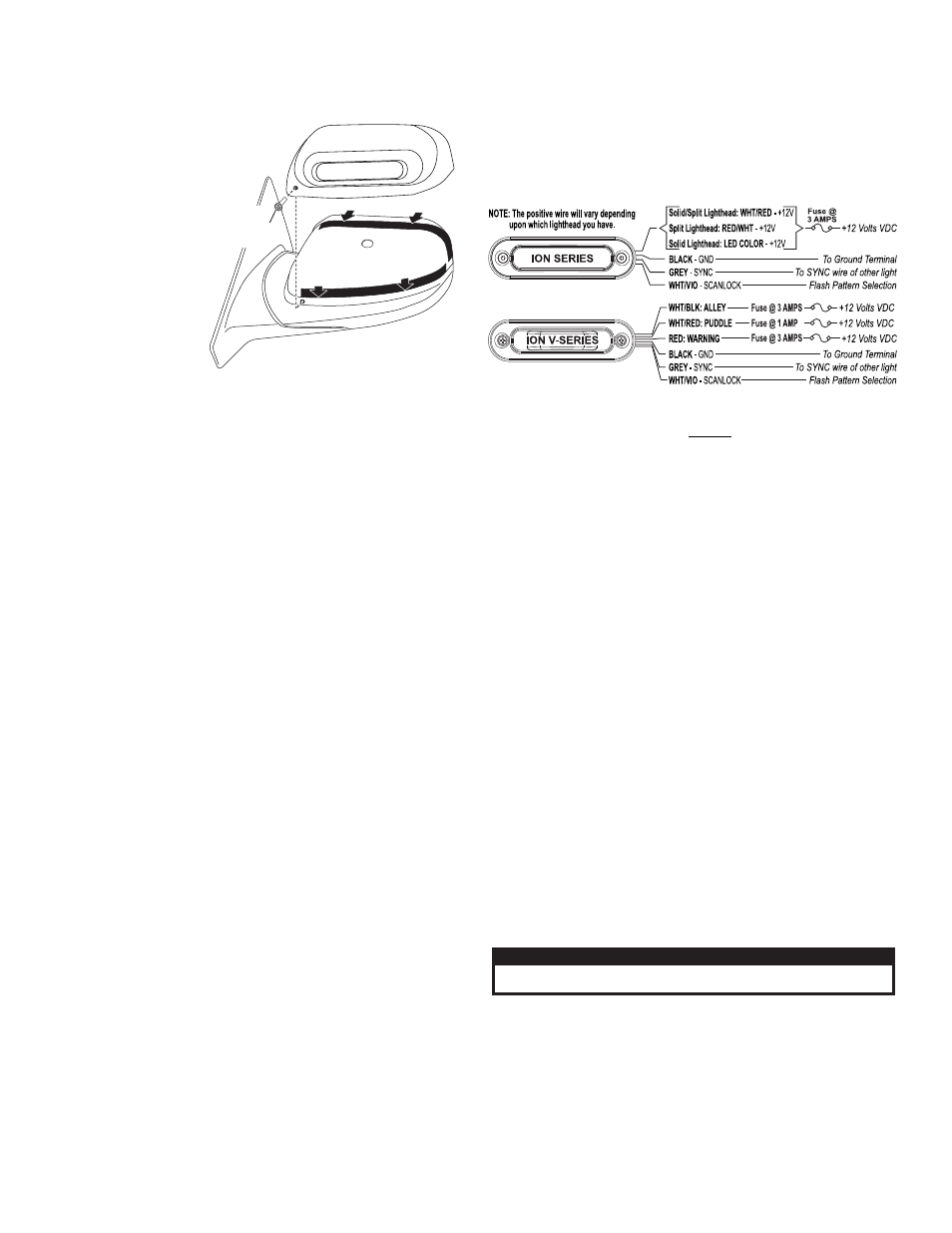
Connecting the Mirror-Beam™ to Power:
1.
Re-connect the mirror assembly to it’s main power cable. Route the
Mirror-Beam™ cable through the door, along the same path as the
vehicle’s main power cable and connect to power.
2.
Cut the non-insulated wire off the Mirror-Beam™ cable. After the
connections are complete, confirm proper operation.
WARNING: All customer supplied wires that connect to the positive
terminal of the battery must be sized to supply at least 125% of the
maximum operating current and FUSED at the battery to carry that
load. DO NOT USE CIRCUIT BREAKERS WITH THIS PRODUCT!
Scan-Lock™ (WHT/VIO) - With the light on: To advance to the next
flash pattern, apply +VDC to the WHT/VIO wire for less than 1 second.
To cycle backwards, apply +VDC to the WHT/VIO wire for more than 1
second. To reset to the factory default pattern, turn off power to the
lighthead. While applying +VDC to the WHT/VIO wire, turn the lighthead
back on. Continue to apply voltage for 5 seconds.
SYNC (GREY) - Lights configured to display the Phase 1 mode of a
pattern will flash simultaneously. Lights configured to display the Phase 2
mode will alternate with any Phase 1 lights with the same pattern.
To sync two lights, configure both lights to display the same Phase 1
pattern. With the power off, connect the GREY wires from each light
together. When the lights are activated, their patterns will be
synchronized. To configure the two lights to alternate their patterns,
advance the pattern of either lights to Phase 2 of the current pattern.
IMPORTANT: It is the responsibility of the installation technician to
make sure that the installation and operation of this product will not
interfere with or compromise the operation or efficiency of any
vehicle equipment!
BOLD = California Title XIII Compliant Pattern
= SYNC Pattern
Italic
PH 1 = Phase 1
PH 2 = Phase 2
SingleFlash 75PH 2
PingPong™ 75PH 1
PingPong 75PH 2
ComAlert™ 75PH 1
ComAlert 75PH 2
LongBurst™ 75PH 1
LongBurst 75PH 2
8.
9.
10.
11.
12.
13.
14.
SingleFlash 60
SingleFlash
SingleFlash 120
SingleFlash 300
DoubleFlash 150
ComAlert™ 150
ActionFlash™ 50
90
ActionFlash™ 150
ModuFlash™
ActionScan™
Steady
15.
17.
18
1
20.
21.
16.
.
9.
22.
23.
24.
25.
SignalAlert™ 75PH 1
SignalAlert 75PH 2
CometFlash® 75PH 1
CometFlash 75PH 2
DoubleFlash 75PH 1
DoubleFlash 75PH 2
SingleFlash 75PH 1
1.
2.
3.
4.
5.
6.
7.
Flash Patterns:
Locate tape at edge of mirror cover
Locate tape at bottom of m
irror
cove
r
#8 X 1/2"
PHILLIPS
T R U S S
S C R E W
CAUTION! DO NOT LOOK DIRECTLY AT THESE LED’S WHILE THEY ARE ON.
MOMENTARY BLINDNESS AND/OR EYE DAMAGE COULD RESULT!
I M P O R TA N T W A R N I N G !
- MBFX11JJ VMFX11AA RSA02ZCR RSA03ZCR RVA03ZCR RSC02ZCR RSC03ZCR RVC03ZCR RSG02ZCR RSG03ZCR IONSMJ IONSMD IONSMM IONSMWJ IONSMWD IONSMWM WIONSMJ WIONSMD WIONSMM WIONSMWJ WIONSMWD WIONSMWM WIONSMCD IONJ IOND IONM IONWJ IONWD IONWM WIONJ WIOND WIONM WIONWJ WIONWD IONA IONWA WIONA WIONWA IONG IONV3A IONV3AW 3SC0CDCR 3SA00FAR 3SBCCDCR 3SRCCDCR 3SR0CDRR IONV1A IONV1AW PAR28DA PAR28DJ UFM8 20C0CDCR 20C0CDCD SFIOND SFIONJ SFIONE SFP1A SFP1G SFP1J SFP1E SFP1D LINZ6K LINZ6J LINZ6D LINZ61 LINZ62 LINZ65 LINZ6A LINZ6A24 LINZ6G IONSMA IONSMWA IONSMCA WIONSMA WIONSMWA WIONSMCA