Page 2 – Whelen PAR36 Super-LED® Work Light User Manual
Page 2
Page 2
WHT - To +12VDC*
BLK - To Ground
WHT - To switched +12VDC*
BLK - To Ground
Voltage -
12Volts DC
Current -
0.85 Amp (6 LED)
1.70 Amp (12 LED)
Voltage -
12Volts DC
Current -
0.85 Amp (6 LED)
1.70 Amp (12 LED)
Voltage -
12Volts DC
Current -
0.85 Amp (6 LED)
1.70 Amp (12 LED)
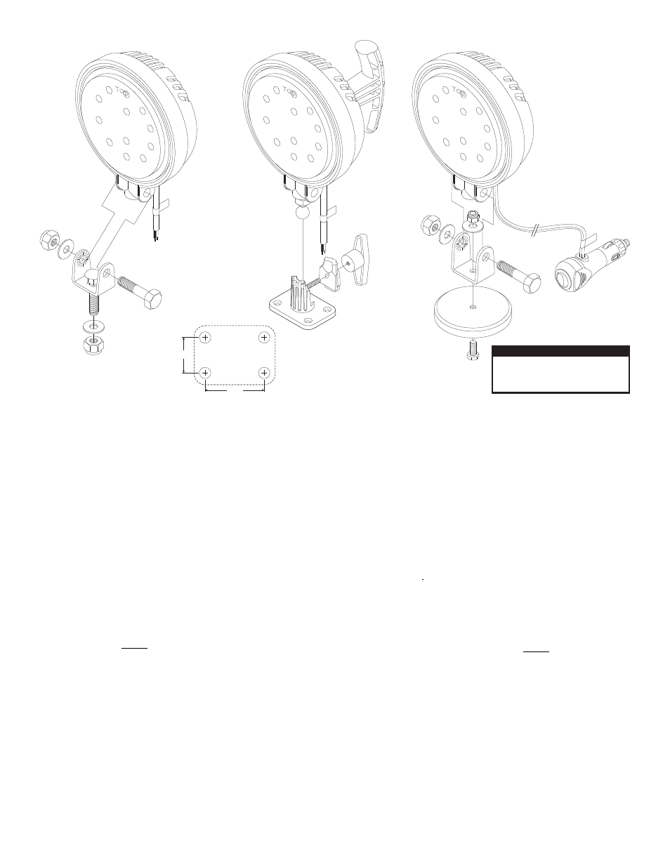
Ball
Base
Hinge
Bracket
Magnet
Adjustment
Knob
*Fuse@3A
*Fuse@3A
Stud Mount...
1.
Position the hinge bracket onto the proposed
mounting surface. Using the bracket as a
template, mark the area where the mounting hole
is to be drilled.
Caution:
Permanent mounting of this product
will require drilling. It is absolutely necessary to
make sure that no other vehicle components could
be damaged by this process. Check both sides of
the mounting surface before starting. If damage is
likely, select a different mounting location.
2.
Drill a clearance hole for a 3/8” bolt. Using the
hardware provided, secure the hinge bolt to the
mounting surface.
3.
Secure the lighthead to the hinge bracket as
shown. When the lighthead is at the desired angle,
tighten the hardware to hold that position.
4.
Using appropriately sized wire, extend the WHT
wire to switched +12VDC. Fuse this wire @3A.
Extend the BLK wire to ground.
WARNING!
All customer supplied wires that
connect to the positive terminal of the battery must
be sized to supply at least 125% of the maximum
operating current and FUSED at the battery to carry
that load. DO NOT USE CIRCUIT BREAKERS WITH
THIS PRODUCT!
IMPORTANT! Before returning the vehicle to active
service, visually confirm the proper operation of this
product, as well as all vehicle components/
equipment.
CAUTION! DO NOT LOOK DIRECTLY AT
THESE LED’S WHILE THEY ARE ON.
MOMENTARY BLINDNESS AND/OR EYE
DAMAGE COULD RESULT!
IMPORTANT WARNING!
Pedestal Mount...
1.
Drill four mounting holes using the template
shown.
Caution:
Permanent mounting of this product
will require drilling. It is absolutely necessary to
make sure that no other vehicle components could
be damaged by this process. Check both sides of
the mounting surface before starting. If damage is
likely, select a different mounting location.
2.
Drill four clearance holes sized for the hardware to
be used (customer supplied) and secure the base
to the mounting surface.
3.
Secure the lighthead ball to the base as shown.
When the lighthead is at the desired angle, tighten
the adjustment knob to hold that position.
4.
Using appropriately sized wire, extend the WHT
wire to +12VDC. Fuse this wire @3A. Extend the
BLK wire to ground.
5.
A push-button on/off switch is located on the rear
of the lighthead.
WARNING!
All customer supplied wires that
connect to the positive terminal of the battery must
be sized to supply at least 125% of the maximum
operating current and FUSED at the battery to carry
that load. DO NOT USE CIRCUIT BREAKERS WITH
THIS PRODUCT!
IMPORTANT! Before returning the vehicle to active
service, visually confirm the proper operation of this
product, as well as all vehicle components/
equipment.
2.00
1.20
Magnetic Mount...
WARNING!
The use of any magnetically mounted
warning device on the outside of a vehicle in motion
is not recommended and is the sole risk and
responsibility of the user.
WARNING!
Thoroughly clean the proposed
mounting surface prior to mounting.
WARNING!
Beacons equipped with cigar cords
are intended for short duration, intermittent
operation only! Prolonged operation requires the
beacon to be permanently wired to the vehicle.
IMPORTANT! Before returning the vehicle to active
service, visually confirm the proper operation of this
product, as well as all vehicle components/
equipment.