Whelen P46S2X User Manual
Whelen For the car
®
ENGINEERING COMPANY INC.
51 Winthrop Road
Chester, Connecticut 06412-0684
Phone: (860) 526-9504
Fax: (860) 526-4078
Sales Email:[email protected]
Canadian Sales:[email protected]
Customer Service:[email protected]
www.
.com
2-color / CA Special PAR-46 LED
Replacement Lamp
Unity® Spotlight
Safety First: This document provides all the necessary information to allow your Whelen product to be properly and safely installed. Before beginning the installation
and/or operation of your new product, the installation technician and operator must read this manual completely. Important information is contained herein that could
prevent serious injury or damage.
For warranty information regarding this product, visit
www.whelen.com/warranty
©2012 Whelen Engineering Company Inc.
Form No. 14601 (061412)
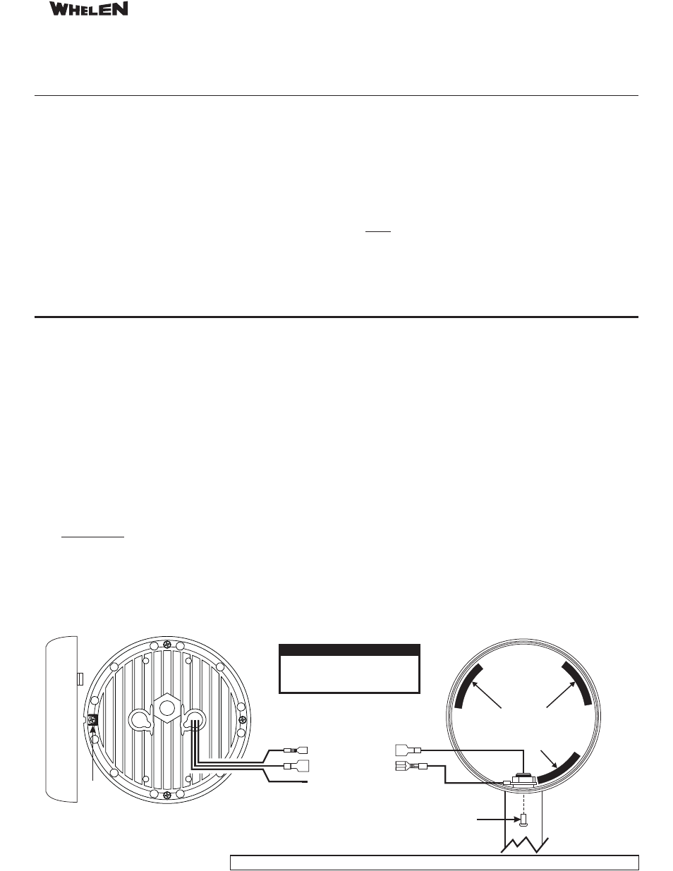
Allen Head
Screw
Lamp
Alignment
Tab
Make sure that the foam
Lamp Stabilizers are in
their original location when
reassembling the housing.
CAUTION! DO NOT LOOK DIRECTLY AT
THESE LEDS WHILE THEY ARE ON.
MOMENTARY BLINDNESS AND/OR EYE
DAMAGE COULD RESULT!
IMPORTANT WARNING!
6B976
RED (to +12VDC)
BLK (Ground)
WHT/VIO (Scan-Lock)
Installation:
1.
2.
3.
4.
With the spotlight turned off, position the housing so that the light is facing
upward.
Locate and remove the Allen Head screw that secures the trim ring to the
housing.
Rotate the trim ring counter-clockwise and remove from the housing.
Note the polarity of the existing wires. Disconnect the wires from the existing
lamp.
5. Connect the spotlight wires to the replacement lamp as shown below. NOTE:
Once the desired pattern has been configured, the Scan-Lock wire (WHT/VIO)
is not needed for operation. Be sure to insulate this wire.
6. Direct the light away from the face and eyes and confirm proper operation of the
spotlight. If the lamp does not operate, check the polarity of the wiring
connections and correct if necessary.
7. With all of the original Lamp Stabilizers in their proper position, tuck the wires
into the housing cavity and place the PAR-46 LED lamp into the housing. The
lamp is properly oriented when the lamp alignment tab is fully seated into the
housing.
8. Return the trim ring to its original position on the housing and secure it in place
using the Allen head screw removed in step #2.
IMPORTANT! Before returning the vehicle to active service, visually confirm the
proper operation of this product, as well as all vehicle components/equipment.
All customer supplied wires that connect to the positive terminal of the
battery must be sized to supply at least 125% of the maximum operating
current and FUSED at the battery to carry that load. DO NOT USE CIRCUIT
BREAKERS WITH THIS PRODUCT!
Operation:
This product essentially functions as two independent lights; A warning light (colored
LEDs) and a spot light (white LEDs). When the light is first turned on (by applying
+12VDC to the Red wire), the warning light will be displayed. Turning the light off and
then immediately back on
spot light. Toggling the power off and on
will switch between the two displays.
The warning light can display a wide variety of flash patterns (see pattern list). As
shown, each warning light flash pattern has two modes. Even numbered patterns will
flash the colored LEDs only. Odd numbered patterns will alternate the colored LEDs
with white LEDs.
To advance thru the patterns, activate the warning light and apply +12VDC to the
WHT/VIO wire for less than 1 second. To cycle backwards,
will activate the
The warning light must be configured to display the desired flash pattern prior to
installation.
apply +12VDC to the
WHT/VIO wire for more than 1 second.
#
Pattern
1
Steady
2/3
SingleFlash 60
4/5
SingleFlash 90
6/7
SingleFlash 120
8/9
DoubleFlash 75
10/11
PingPong 75
12/13
DoubleFlash 120
Flash Patterns:
14/15
PingPong 120
16/17
TrippleFlash™ 75
18/19
TrippleFlash 120
20/21
Sig-Alert Cal
22/23
Action/SingleFlash I
24/25
Action/SignalFlash II
26/27
CalScan™
• Proper installation of this product requires the installer to have a good
understanding of automotive electronics, systems and procedures.
• If mounting this product requires drilling holes, the installer MUST be sure that no
vehicle components or other vital parts could be damaged by the drilling process.
Check both sides of the mounting surface before drilling begins. Also de-burr any
holes and remove any metal shards or remnants. Install grommets into all wire
passage holes.
• Do not install this product or route any wires in the deployment area of your air bags.
Equipment mounted or located in the air bag deployment areas will damage or
reduce the effectiveness of the air bag, or become a projectile that could cause
serious personal injury or death. Refer to your vehicle owner's manual for the air
bag deployment areas. The User/Installer assumes full responsibility to determine
proper mounting location, based on providing ultimate safety to all passengers
inside the vehicle.
• For this product to operate at optimum efficiency, a good electrical connection to
chassis ground must be made. The recommended procedure requires the product
ground wire to be connected directly to the NEGATIVE (-) battery post.
• If this product uses a remote device to activate or control this product, make sure
that this control is located in an area that allows both the vehicle and the control to
be operated safely in any driving condition.
•
Do not attempt to activate or control this device in a hazardous driving situation.
•
This product contains either strobe light(s), halogen light(s), high-intensity LEDs or
a combination of these lights. Do not stare directly into these lights. Momentary
blindness and/or eye damage could result.
•
Use only soap and water to clean the outer lens. Use of other chemicals could result
in premature lens cracking (crazing) and discoloration. Lenses in this condition
have significantly reduced effectiveness and should be replaced immediately.
Inspect and operate this product regularly to confirm its proper operation and
mounting condition. Do not use a pressure washer to clean this product.
•
FAILURE TO FOLLOW THESE
PRECAUTIONS AND INSTRUCTIONS COULD
RESULT IN DAMAGE TO THE PRODUCT OR VEHICLE AND/OR SERIOUS INJURY TO
YOU AND YOUR PASSENGERS!
WARNING! All customer supplied wires that connect to the positive (+) terminal of
the battery must be sized to supply at least 125% of the maximum operating current
and
“at the battery” to carry that load. DO NOT USE CIRCUIT BREAKERS
WITH THIS PRODUCT!
•
FUSED