Page 2 – Whelen MPBW User Manual
Page 2
Page 2
2
2
2
2
2
2
2
2
2
2
2
2
2
2
2
2
*
*
*
*
3
3
3
3
3
3
3
3
4
4
4
4
4
4
4
4
1
1
1
1
1
1
1
1
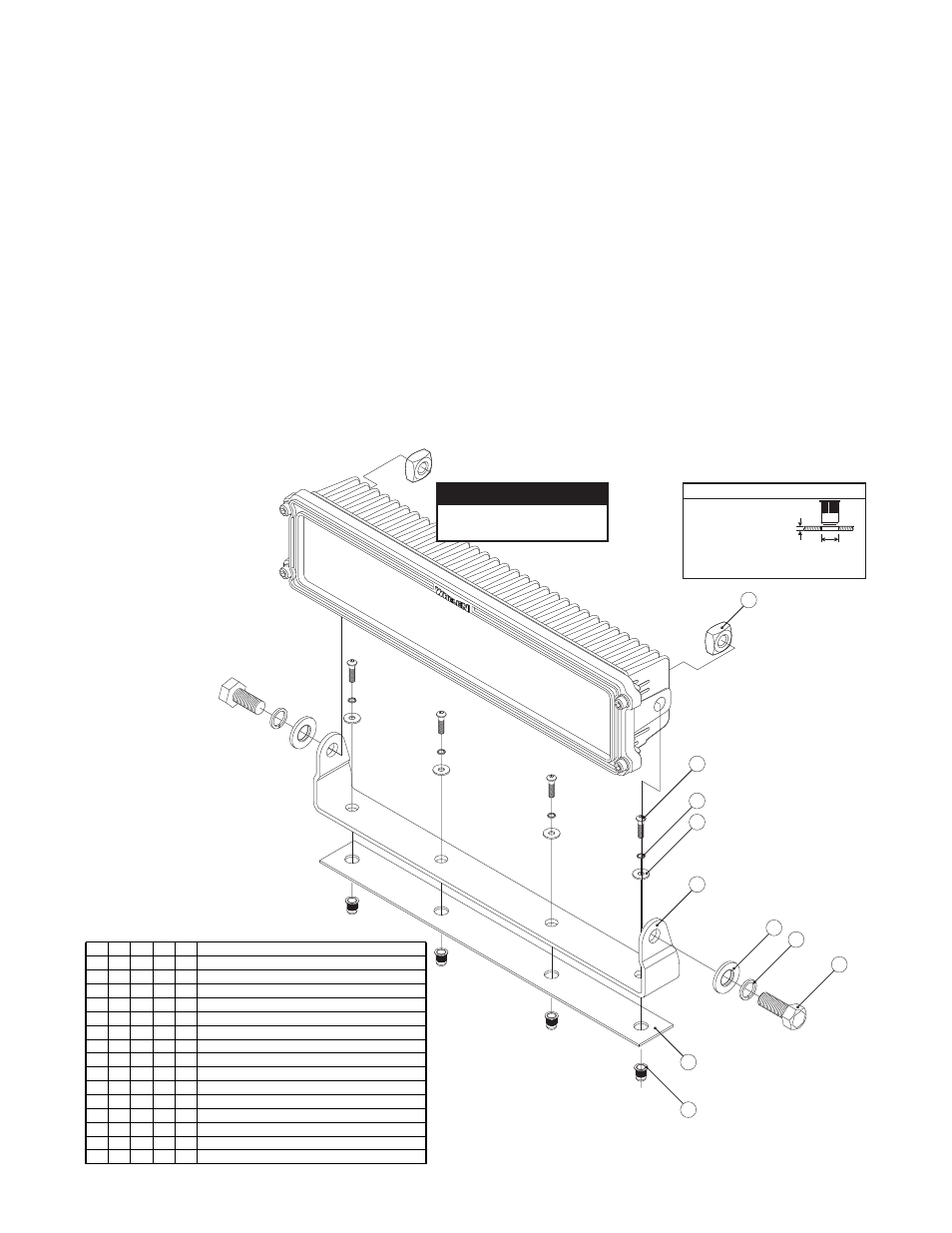
ITEM
DESCRIPTION
QTY
QTY
QTY
QTY
2
3
4
5
6
7
8
9
10
1
3/8 Washer, Flat
5/16 - 18 Riv Nut
Bracket, Bail
Seal
3/8 Washer, Split-Lok S.S.
5/16 Washer, Split-Lok
5/16 Washer, Flat
Nut, 3/8-16 Square, Brass
Screw, 5/16-18 x 1 1/8 Button Head
Screw, 3/8
4 Hex
X 1 1/
S.S.
Bail Mount Kit, Pioneer, Single
Bail Mount Kit, Pioneer, Dual / Max / Quad
Bail Mount Kit, Pioneer Slimline, Single
Bail Mount Kit, Pioneer Slimline, Dual
1
2
3
4
5
6
7
8
10
9
Pioneer Slimline Dual
shown for reference only.
CAUTION-Hot Surface!
Make sure to route all wires
away from the heat sink fins.
Mounting Surface
Material Thickness:
Min. - 0.027
Max. - 0.150
Hole Size (Dia.):
Min. - 0.531
Max. - 0.537
Mounting Hole Specifications
This manual will outline bail bracket installation procedures for the
Pioneer-series light. With the exception of the Micro Pioneer, all of the bail
bracket mounting kits use identical hardware to secure the bracket to its
mounting surface. Refer to Page 3 for information on mounting the Micro
Pioneer.
Mounting...
CAUTION: Mounting this product will require drilling. It is absolutely
necessary to make sure that no other vehicle components could be
damaged by this process. Check both sides of the mounting surface
before starting. If damage is likely, select a different mounting
location.
1. Position the appropriate bail bracket (Item #5) onto the proposed
mounting surface. Mark the areas where the mounting holes are to be
drilled.
2. Drill the mounting holes required using an appropriately sized drill bit
(refer to the Mounting Hole Specifications shown below).
IMPORTANT NOTE! This installation uses Rivnuts to secure the
brackets to the vehicle. This type of hardware requires the use of a
specialized installation tool. Refer to the owners manual included
with this tool for proper installation techniques. Be sure to follow the
mounting hole specifications precisely!
3. With the Rivnuts properly installed, position the appropriate seal (#9)
over the mounting holes and position the mounting bracket onto the
seal. The bracket can now be mounted onto the vehicle using the
appropriate hardware (Items #2, #3 & #4). Insert the bolts into their
holes with the hardware shown.
4. Apply a drop of LocTite 242 to each of the mounting bolts and insert
them into their Rivnut. Tighten each bolt to 50 in/lbs.
5. Insert the two brass hex nuts (Item(s) #1) into the cavity provided in the
rear of the Pioneer housing. Now position the Pioneer housing into its
mounted position on the bail bracket. Using the hardware provided
(Items #6, #7 & #8) secure the housing assembly onto the bail bracket.
6. Adjust the floodlight to the desired angle and tighten the hardware firmly
to maintain that angle (minimum 20 foot-pounds)
7. Extend the Pioneer wires towards it’s designated power source. Make
the necessary connections using the information found in the following
section.
Wiring...
Refer to the wiring guide included with your Pioneer for wire
functions, fuse values and optional switch connections.
IMPORTANT! Before returning the vehicle to active service, visually
confirm the proper operation of this product, as well as all vehicle
components/equipment.