Pioneer dimensions, Caution-hot surface, Page 2 – Whelen PBA106 User Manual
Page 2
Page 2
Pioneer Dual Shown
For Reference Only
Mounting Surface
Material Thickness:
Min. - 0.027
Max. - 0.150
Hole Size (Dia.):
Min. - 0.531
Max. - 0.537
Mounting Hole Specifications
1
2
4
5
6
7 8
9
11
12
10
16
17
3
13 14
15
0 7 - 2 4 3 7 3 5 - 0 0 0
1 6 - 1 5 0 3 2 2 0 - 6 0
1 6 - 1 4 0 2 4 2 0 - 0 5
0 7 - 2 6 B 0 9 0 - 0 0 1
0 7 - 2 8 6 0 8 4 - 0 0 1
0 7 - 2 8 6 0 8 2 - 0 0 1
3 8 - 0 2 4 3 7 3 6 - 0 0
3 8 - 0 2 4 3 6 6 9 - 0 0
1 6 - 1 5 3 2 2 2 0 - 1 0
1 6 - 1 4 3 1 9 2 0 - 0 8
1 4 - 1 4 8 B 2 6 - 1 8 0
1 4 - 1 3 0 5 3 6 - 0 4 M
1 3 - 1 4 8 F 1 8 - 0 0 0
2
4
4
4
4
4
4
3
3
3
3
4
1
1
1
-
-
-
-
4
4
4
4
4
4
4
4
4
4
2
2
-
-
-
-
-
-
-
-
1
1
1
1
1
1
ITEM
PART NUMBER
DESCRIPTION
0 1 - 0 4 8 6 0 8 4 - 0 0
0 1 - 0 4 8 6 0 8 2 - 0 0
0 1 - 0 4 6 B 0 9 0 - 0 0
1 4 - 1 5 6 B 3 6 - 1 2 0
QTY
QTY
QTY
4
4
4
2
3
4
5
6
7
8
9
10
11
12
13
14
15
16
17
1
Light Bracket , Floodlight
3/8 Flat Washer, S.S.
5/16
S.S.
Flat Washer,
Horizontal Mounting Bracket (Single)
Horizontal Mounting Bracket (Dual)
Vertical
(Dual)
Mounting Bracket
Seal (Single)
Seal (Dual)
3/8 Washer, Split-Lok S.S.
5/16
S.S.
Washer, Split-Lok
Soc. Button Head Screw, 3/8-16 X 3/4 S.S.
Soc.
5/16-18 X 1 1/8 S.S.
Button Head Screw,
Screw, 1/4-20 X 1/4 Socket set S.S. w/Cup Point
Rivnut 5/16-18
Pioneer™ (Single) Mounting Kit - Horizontal Mount
Pioneer™ (Dual) Mounting Kit - Horizontal Mount
Pioneer™ (Dual) Mounting Kit - Vertical Mount
Pioneer Mounting Bracket, Single
Pioneer Mounting Bracket, Dual
Screw, #10- 24 X 3/8 PFHMS, S.S.
0 7 - 2 4 3 9 0 1 - 0 0 1
0 7 - 2 6 B 8 5 4 - 0 0 1
1 4 - 1 0 4 11 6 - 0 6 0
3
4
4
PART NUMBER
DESCRIPTION
Pioneer™ Series LED Floodlight (Single)
Pioneer Series
LED Floodlight (Single)
PLUS
Pioneer
eries LED Floodlight (Dual)
S
Pioneer
eries
LED Floodlight (Dual)
S
PLUS
0 1 - 0 6 8 6 4 8 9 _ _ _
0 1 - 0 6 8 6 4 4 9 _ _ _
0 1 - 0 6 8 6 4 8 7 _ _ _
0 1 - 0 6 8 6 4 4 8 _ _ _
Pioneer Dimensions
8.18"
4.25"
Pioneer (Single)
4.25"
14.05"
Pioneer (Dual)
01-0686136_ _ _
-00 = 12V / White
-01 = 12V / White (15' (Dual Only))
-02 = 12V / Black (15'
)
-07 = 12V / Black
-24 = 24V / White
-27 = 24V / Black
D27= 24V / Desert Sand
(Dual Only)
(Pioneer Plus-only)
Sample Part Number Key
2.80"
CAUTION-Hot Surface!
Make sure to route all wires
away from the heat sink fins.
Mounting...
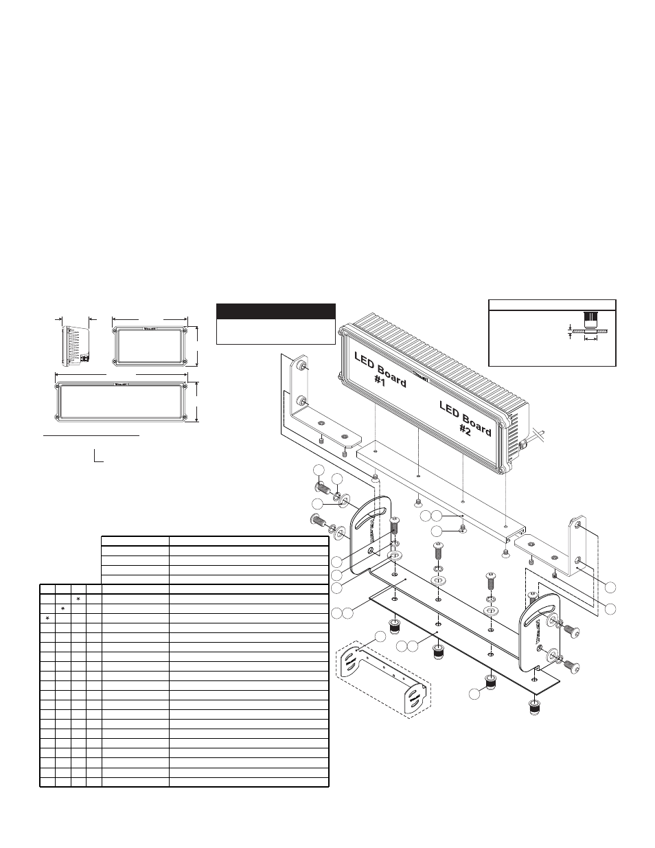
1. Position the appropriate mounting bracket (Item #7 or #8) onto the
proposed mounting surface. Mark the areas where the mounting
holes are to be drilled.
2. Drill the mounting holes required using an appropriately sized drill
bit (refer to the Mounting Hole Specifications shown below).
IMPORTANT NOTE! This installation uses Rivnuts to secure the
brackets to the vehicle. This type of hardware requires the use of
a specialized installation tool. Refer to the owners manual
included with this tool for proper installation techniques. Be sure
to follow the mounting hole specifications precisely!
3. With the Rivnuts properly installed, position the appropriate seal
(#9 or #10) over the mounting holes and position the mounting
bracket onto the seal. The floodlight can now be mounted onto the
vehicle using the appropriate hardware (Items #4, #5 & #6). Insert
the bolts into their holes with the hardware shown.
4. Apply a drop of LocTite 242 to each of the four mounting bolts and
insert them into their Rivnut. Tighten each bolt to 50 in/lbs.
5. Secure the appropriate Pioneer mounting bracket (Item #12 or #13)
to the Pioneer assembly using Item #14 (apply a drop of LocTite®
242 to the threads). Insert the floodlight brackets (Item #16) into the
mounting bracket as shown. Secure these brackets using the
hardware provided (#15).
6. Using the appropriate hardware (Items #1, #2 & #3), install the
floodlight assembly onto the mounting bracket.
7. Adjust the floodlight to the desired angle and tighten the hardware
firmly to maintain that angle.
Wiring...
All customer supplied wires that connect to the positive terminal
of the battery must be sized to supply at least 125% of the
maximum operating current and FUSED at the battery to carry
that load. DO NOT USE CIRCUIT BREAKERS WITH THIS
PRODUCT!
Refer to the wiring guide included with your Pioneer for wire
functions, fuse values and optional switch connections.
IMPORTANT! Before returning the vehicle to active service,
visually confirm the proper operation of this product, as well as
all vehicle components/equipment.