Whelen PSA00FAR User Manual
Important warning
®
ENGINEERING COMPANY INC.
51 Winthrop Road
Chester, Connecticut 06412-0684
Phone: (860) 526-9504
Fax: (860) 526-4078
Sales Email:[email protected]
Canadian Sales:[email protected]
Customer Service:[email protected]
www.
.com
Strip-Lite™ Series LED Lighthead
Safety First: This document provides all the necessary information to allow your Whelen product to be properly and safely installed. Before beginning the installation
and/or operation of your new product, the installation technician and operator must read this manual completely. Important information is contained herein that could
prevent serious injury or damage.
Mounting:
Scan-Lock™ - White/Violet
1.
Mark the location of the 2 mounting holes onto the mounting surface using the
dimensions shown, or remove the lens and use it as a template. Always check behind
the mounting surface to be sure you will not harm other vehicle components.
2.
Drill the 2 mounting holes using a drill sized for a #6 sheet metal screw, then drill the
5/8” wire access hole 0.975” inboard of the mounting hole as shown.
3.
Feed wires through wire hole then secure Strip-Lite™ to mounting surface with the
supplied hardware.
apply +12 volts to the WHITE/VIOLET wire for less
than 1 second and release.
apply +12 volts to the WHT/VIO wire for more
than 1 second and release.
When the desired pattern is displayed, allow it to run for more than 5 seconds. The
lighthead will now display this pattern when initially activated.
With the lighthead off, apply +12 volts to the WHT/VIO wire. Turn the lighthead on. The
factory default pattern will now be displayed.
CHANGING PATTERNS:
CHANGING THE DEFAULT PATTERN:
TO RESTORE THE FACTORY DEFAULT PATTERN:
To advance to the next pattern
To cycle back to the previous pattern
A Normally Open momentary switch is best suited for Scan-Lock operation.
For warranty information regarding this product, visit
www.whelen.com/warranty
©2002 Whelen Engineering Company Inc.
Form No. 13713G (092513)
•
Proper installation of this product requires the installer to have a good understanding of
automotive electronics, systems and procedures.
•
Whelen Engineering recommends the use of waterproof butt splices and/or connectors if that
connector could be exposed to moisture.
•
If mounting this product requires drilling holes, the installer MUST be sure that no vehicle
components or other vital parts could be damaged by the drilling process. Check both sides
of the mounting surface before drilling begins. Also de-burr any holes and remove any metal
shards or remnants. Install grommets into all wire passage holes.
•
Do not install this product or route any wires in the deployment area of your air bag.
Equipment mounted or located in the air bag deployment area will damage or reduce the
effectiveness of the air bag, or become a projectile that could cause serious personal injury
or death. Refer to your vehicle owner's manual for the air bag deployment area. The
User/Installer assumes full responsibility to determine proper mounting location, based on
providing ultimate safety to all passengers inside the vehicle.
•
For this product to operate at optimum efficiency, a good electrical connection to chassis
ground must be made. The recommended procedure requires the product ground wire to be
connected directly to the NEGATIVE (-) battery post.
•
If this product uses a remote device to activate or control this product, make sure that this
control is located in an area that allows both the vehicle and the control to be operated safely
in any driving condition.
•
Do not attempt to activate or control this device in a hazardous driving situation.
•
This product contains either strobe light(s), halogen light(s), high-intensity LEDs or a
combination of these lights. Do not stare directly into these lights. Momentary blindness
and/or eye damage could result.
•
Use only soap and water to clean the outer lens. Use of other chemicals could result in
premature lens cracking (crazing) and discoloration. Lenses in this condition have
significantly reduced effectiveness and should be replaced immediately. Inspect and operate
this product regularly to confirm its proper operation and mounting condition. Do not use a
pressure washer to clean this product.
•
W
•
FAILURE TO FOLLOW THESE
PRECAUTIONS AND INSTRUCTIONS COULD RESULT IN
DAMAGE TO THE PRODUCT OR VEHICLE AND/OR SERIOUS INJURY TO YOU AND YOUR
PASSENGERS!
ARNING! All customer supplied wires that connect to the positive (+) terminal of the battery
must be sized to supply at least 125% of the maximum operating current and
“at the
battery” to carry that load. DO NOT USE CIRCUIT BREAKERS WITH THIS PRODUCT!
FUSED
CAUTION! DO NOT LOOK DIRECTLY AT THESE LEDS WHILE THEY ARE ON.
MOMENTARY BLINDNESS AND/OR EYE DAMAGE COULD RESULT!
IMPORTANT WARNING!
Compartment
Light
Warning or
Flasher Light
Brake/Tail/Turn
Fuse all +VDC wires @ 3 Amps
Brake/Tail/Turn
(Amber Turn)
Tank Fluid
Level
Steady Burn
Brake (Steady)
Brake (Steady)
Steady
Default
Pattern
Wiring
Fusing
SignalAlert™
YEL
BRN
WHT
(Brake) - +12VDC
(Tail) - +12VDC
- Ground
LED
Color - +12VDC
Ground
BLK -
Ground
LED
Color - +12VDC
-
BLK
- Scan-Lock
WHT/VIO
WHT - +24VDC
or
BLK/WHT - Ground
- Scan-Lock™
Note:48 & 96 LED only
WHT/VIO
RED
BRN
YEL
GRN
WHT -
(Brake) - +12VDC
(Tail) - +12VDC
(L. Turn) - +12VDC
(R. Turn) - +12VDC
Ground
BLK - Ground
WHT - +12VDC
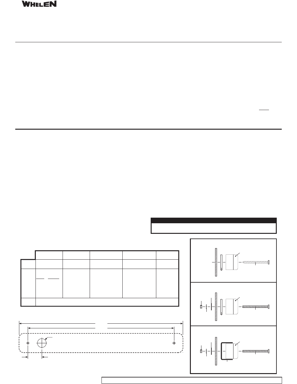
Locate wire hole .975" inboard of mounting hole.
.625" Dia.
FRONT VIEW
10.25”
11.50”
It is the responsibility of the installation technician to make sure that the installation
and operation of this product will not interfere with or compromise the operation or
efficiency of any vehicle equipment!
Before returning the vehicle to active service, visually confirm the proper operation of
this product, as well as all vehicle components/equipment.
Standard Patterns
ModuFlash™
SignalAlert™ 150
SignalAlert 75
SignalAlert Steady
1.
DoubleFlash 150
2.
DoubleFlash 75
3.
4.
9.
10.
CometFlash® 75
ActionFlash™
SingleFlash 375
SingleFlash 150
5.
6.
7.
8.
11.
12.
15. Steady (Brake)
SingleFlash 15
SingleFlash 75
1.
Brake (Steady)
2.
SignalAlert™ Steady
13.
14.
ComAlert™
ActionScan™
Brake/Tail/Turn Patterns
Flat
Washer
Flat
Washer
Strip-Lite
Strip-Lite™
MOUNTING STYLE #1
MOUNTING STYLE #2 (Hardware Not Included)
MOUNTING STYLE #3 (Hardware Not Included)
Strip-Lite
Strip-Lite
Guard P/N: 07-26B102-000
(Optional)
Gasket
Gasket
#6 x 1 1/4
Sheet Metal Screw
#6 x 1 1/4
Machine Screw
#6 x 1 1/4
Machine Screw
Split
Lockwasher
Split
Lockwasher
Nut
Nut