Fig. 3, Fig. 2, Fig. 1 – Whelen L6BKT5 User Manual
Page 2: Installation
Page 2
6 X 3/4 PPHSMS
8-32 X 1" PPHMS
8-32 HEX NUT
#8 INTERNAL TOOTH
LOCK WASHER
Mounting Flange
Mirror
B as
e
Lighthead
Surface
Mount
Flange
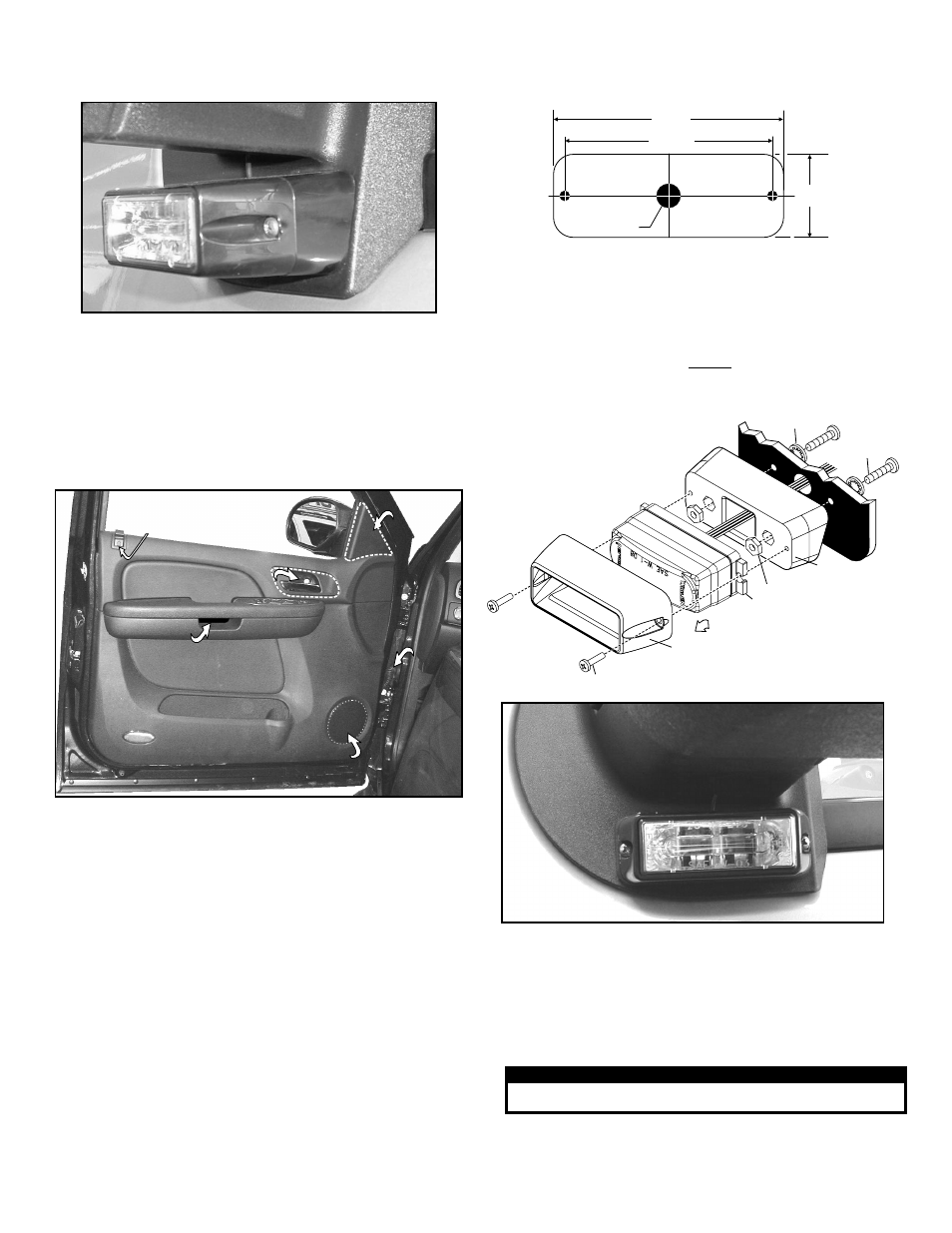
NOTE: The surface mount flange included
with the LINZ6™ is not needed for this
installation. Use the flange included with
the surface mount kit (shown here).
10mm bolt
under cover
10mm bolt
under cover
Remove speaker after
removing door panel
Remove speaker after
removing door panel
10mm bolt
under cover
DOOR OPENER
DOOR PULL
Remove cover,
remove two
10mm bolts
Remove cover,
remove two
10mm bolts
Remove cover,
remove two
10mm bolts
Remove
mirror
inner
cover
Remove
mirror
inner
cover
Fig. 2
Remove speaker after
removing door panel
Window lock
set screw
behind cap
Wire
Harness
Boot
Wire
Harness
Boot
Wire
Harness
Boot
Remove
mirror
inner
cover
Fig. 1
LINZ6™ Mounting Bracket L6BKT5 - This bracket mounts to the base
of the mirror mount, on the driver or passenger side mirror.
To Remove the Side Mirror Assembly:
1.
Remove the cover from behind the door pull and remove the two
10mm bolts underneath (Fig. 2).
2.
Remove the triangular cover covering the inside of the mirror base.
Remove the three bolts underneath the cover that hold the mirror
assembly on then remove the mirror assembly from the vehicle.
3.
Locate the small cover behind the door opener, pull it off and remove
the 10mm bolt underneath.
4.
There are 16 snap-in fasteners located around the door panel.
Carefully pry the door panel loose but do not remove the panel yet.
5.
Unplug the 3 connectors behind the door pull. IMPORTANT: Be sure
to remember where the connectors plug in for reassembly.
6.
Remove the door lock button and pull the door panel off then unplug
the wire harness that goes to the mirror.
Installation:
1.
Mark the mounting hole measurements off onto the mounting
surface.
2.
Drill the two mounting holes. In the center drill a .375 diameter wire
passage hole into the mirror base.
3.
Secure the lighthead by first securing the mounting flange to the
mirror and then the lighthead to the mounting flange as shown.
4.
Following the factory wire harness, extend the wires to your power
source and refer to the lighthead manual for hookup and fusing.
5.
Remount mirror and reassemble door and installation is complete.
WARNING! All customer supplied wires that connect to the positive
terminal of the battery must be sized to supply at least 125% of the
maximum operating current and FUSED at the battery to carry that
load. DO NOT USE CIRCUIT BREAKERS WITH THIS PRODUCT!
IMPORTANT! Before returning the vehicle to active service,
visually confirm the proper operation of this product, as well as all
vehicle components/equipment.
IMPORTANT! It is the responsibility of the installation technician to
make sure that the installation and operation of this product will not
interfere with or compromise the operation or efficiency of any
vehicle equipment!
Fig. 3
3.6"
1.3"
.375" Wire
Passage Hole
3.25"
CAUTION! DO NOT LOOK DIRECTLY AT THESE LED’S WHILE THEY ARE ON.
MOMENTARY BLINDNESS AND/OR EYE DAMAGE COULD RESULT!
I M P O R TA N T W A R N I N G !