Specifications, Mounting, Wiring / power – Whelen ALPHASL User Manual
Page 2: Control switches, Speakers, Operation, Siren amplifier, Page 2
Page 2
#10 X 3/4"
PPHSMS
16 Position
I n p u t
Connector
Scan-Lock™
Fuse
Trunk
W a l l
Trunk
W a l l
Trunk
W a l l
• Compact design
• Power to drive two 100 watt speakers
• Title 13 compliant operation
• Scan-Lock™ siren tone programming
• Hands Free operation
• Simulated mechanical wail tone
• 3 Programmable modes of operation
• Harmonically rich composite air horn tones
Congratulations on selecting the Alpha SL Siren. This siren offers a unique and distinctive collection of features designed to allow the
user to customize the operation of this siren to suit their individual needs. Features include:
Specifications:
Input Voltage . . . . . . . . . . . . . . . . . . . . . . . . . . . . . . . . 12.8 V DC
Input Current: . . . . . . .@ 15 V DC @ 5.5 OHMS 16 AMPS Max.
Input Fuse . . . . . . . . . . . . . . . . . . . . . . . . . . . . . . . . . . . 20 amps
Speaker Impedance . . . . . . . . . . . . . . . . . . . 5.5 ohms Minimum
Operating Temperature . . . . . . . . . . . . . . . . . . .-30°C. to +60°C
Storage Temperature . . . . . . . . . . . . . . . . . . . . .-40° C to +70°C
Humidity. . . . . . . . . . . . . . . . . . . . . . . . . . . 99% Non condensing
Output Voltage . . . . . . . @15 V DC @ 11 ohms 34V RMS Max.
Output Power . . . . . . . .@ 15 V DC @ 11 ohms 105 Watts Max.
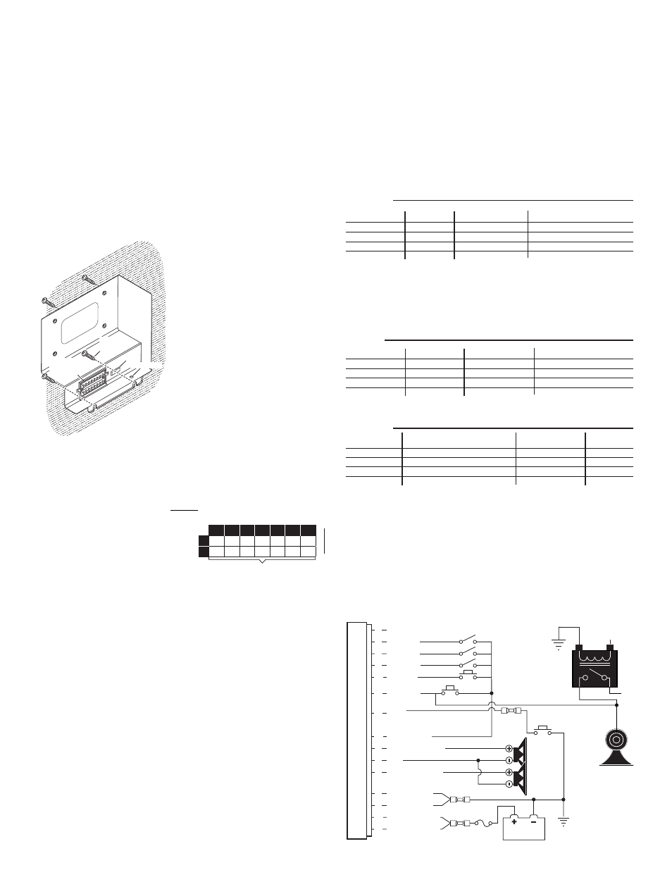
Mounting:
1.
Locate a suitable mounting
location. The vertical wall
between the trunk and the
passenger compartment is often
a good choice and is the method
described in this manual.
2.
Be sure that the remote amplifier
fits properly and does not
interfere with any parts of the
trunk lid or seat back.
3.
Position the amplifier onto the
mounting location. Using an awl or
other suitable tool, scribe the
mounting surface where the
mounting holes are to be drilled.
4.
Carefully drill the mounting holes using a #16
drill bit.
5.
Using the supplied #10 x 3/4” sheet metal screws, secure
the remote amplifier to the vertical trunk wall.
Wiring / Power:
WARNING! All customer supplied wires that connect to the positive
terminal of the battery must be sized to supply at least 125% of the
maximum operating current and FUSED at the battery to carry that load.
DO NOT USE CIRCUIT
BREAKERS WITH THIS
PRODUCT!
1.
Extend the two (2)
RED wires along the
factory wiring harness
to the POSITIVE +12VDC battery terminal.
2.
Connect the RED wires to one end of a user supplied fuse block.
Do not connect this fuse block to the battery yet.
3.
Extend the two (2) BLACK wires along the factory wiring harness to
the NEGATIVE battery terminal.
Control Switches:
This siren amplifier has six control inputs available, however; not all
control inputs will need to be wired depending on the “Mode of Operation”
chosen by the user. Five of the control inputs (CNTRL 1-3, air horn and
horn ring) are activated by applying positive voltage (Vbat) to them, the
RED/WHITE wire (pin 14) is a current limited output that can be used for
this purpose (see wiring diagram).The last input (CYCLE) is activated by
applying ground to it. Refer to the Air bag warning on Page 1 before
extending any wires into the interior of the vehicle.
Speakers:
1.
Extend the ORANGE, YELLOW and BROWN wires along the factory
wiring harness towards your speakers.
2.
Connect YELLOW wire to POSITIVE (+) terminal of speaker #1 and
ORANGE wire to POSITIVE (+) terminal on speaker #2.
3.
Connect BROWN wire to NEGATIVE (-) terminal on both speakers.
Operation:
Siren in use: This output will become active (+VBAT) whenever a tone is
being produced by the siren.
Modes: There are 3 modes of operation. Mode 1 is the factory default
mode. See “Mode Programming” to change the mode of operation.
20
18
16
14
12
5
INS
7.5
4
12
6
19.5
9.5
31
15.5
10
20
22
3
INS
Wire Gauge / AWG
TABLE
1
Current
D r a w
A M P S
Distance in Feet
10
49
24.5
3
8
9
10
11
12
13
14
5
6
CHASSIS
GROUND
BATTERY
N/C
WHT/RED
WHT/ORG
WHT/YEL
WHT/GRN
GRN
BLU - Siren in Use
RED/WHT +V
ORG - Speaker #1
YEL - Speaker #2
1
2
15
16
BLK - Ground
BLK - Ground
RED - (+12 VDC)
RED - (+12 VDC)
Siren
Amplifier
W i r i n g D i a g r a m
20 AMP
FUSE
4
BRN
Siren
Speaker
Siren
Speaker
7
WHT/BRN
Activation Switch
CNTRL 1
Cycle
Switch
CNTRL 2
CNTRL 3
AIR HORN
ALTERNATIVE CONNECTION
HORN
RELA
Y
+12V
VEHICLE
HORN
TO HORN
BUTTON
HORN RING
C
ONTROL
-
input O
PERATION
A
IR
H
ORN
-
switch* H
ORN
R
ING
C
YCLE
-
&
switch
C N T R L 1
C N T R L 2
C N T R L 3
A I R H O R N *
Wail
Yelp
HF-Standby
Airhorn
A i r h o r n
A i r h o r n
A i r h o r n
A i r h o r n
Yelp
Piercer
Airhorn
HF cycle (Wail, Yelp,
)
Piercer
HF cycle (Wail, Yelp,
)***
Piercer
*** HF cycle: tones are activated by a single tap on the hornring or cycle switch.
The first tap produces a WAIL tone (a steady rise and fall tone). A second tap
produces a YELP tone (a fast rise and fall tone). A third tap produces a
The next tap returns the siren to a wail tone and the cycle repeats itself.
Two
successive taps will stop the siren.
tone.
quick
***
***
***
Piercer
***
* The AIRHORN switch produces airhorn as a main tone as well as an override tone.
C
ONTROL
/
input
O
PERATION
A
IR
H
ORN
/
switch* H
ORN
R
ING
C
YCLE
/
&
switch
C N T R L 1
C N T R L 2
C N T R L 3
A I R H O R N *
Wail
Yelp
MANUAL-Stby
Airhorn
A i r h o r n
A i r h o r n
A i r h o r n
A i r h o r n
Yelp
Wail coast
stop
Airhorn
Piercer
,
to
* The AIRHORN switch produces airhorn as a main tone as well as an override tone .
M
ODE
1
M
ODE
2
The following tables show the factory default tone settings. See the "Siren tone
programming procedures" section to make desired changes.
C
ONTROL
/
input O
PERATION
A
IR
H
ORN
/
switch*
H
ORN
R
ING
C
YCLE SWITCH
&
C N T R L 1
C N T R L 2
C N T R L 3
A I R H O R N *
Wail
Instant** HF (Wail, Yelp,
)
Instant** MANUAL (Wail, Coast)
Airhorn
Piercer
A i r h o r n
A i r h o r n
A i r h o r n
A i r h o r n
Yelp
No Change
No Change
Airhorn
*** HF cycle: tones are activated by a single tap on the CNTRL2 switch. The first tap
produces a WAIL tone (a steady rise and fall tone). A second tap produces a
YELP tone (a fast rise and fall tone). A third tap produces a
tone .
tap returns the siren to a wail tone and the cycle repeats itself.
successive taps will stop the siren.
***
***
***
***
Piercer™
The next
The next
** The word 'instant' implies that activating CNTRL2 will generate the HF cycle on
it's own , and that activating CNTRL3 will generate the Manual tone on it's own.
CNTRL 2 & 3 should be momentary switches for this application.
**
**
* The AIRHORN switch produces
as a main tone as well as an override
tone .
AIR HORN
*
M
ODE
3