Model pcc4w, Mounting, Wiring – Whelen PCC4W User Manual
Page 2
Page 2
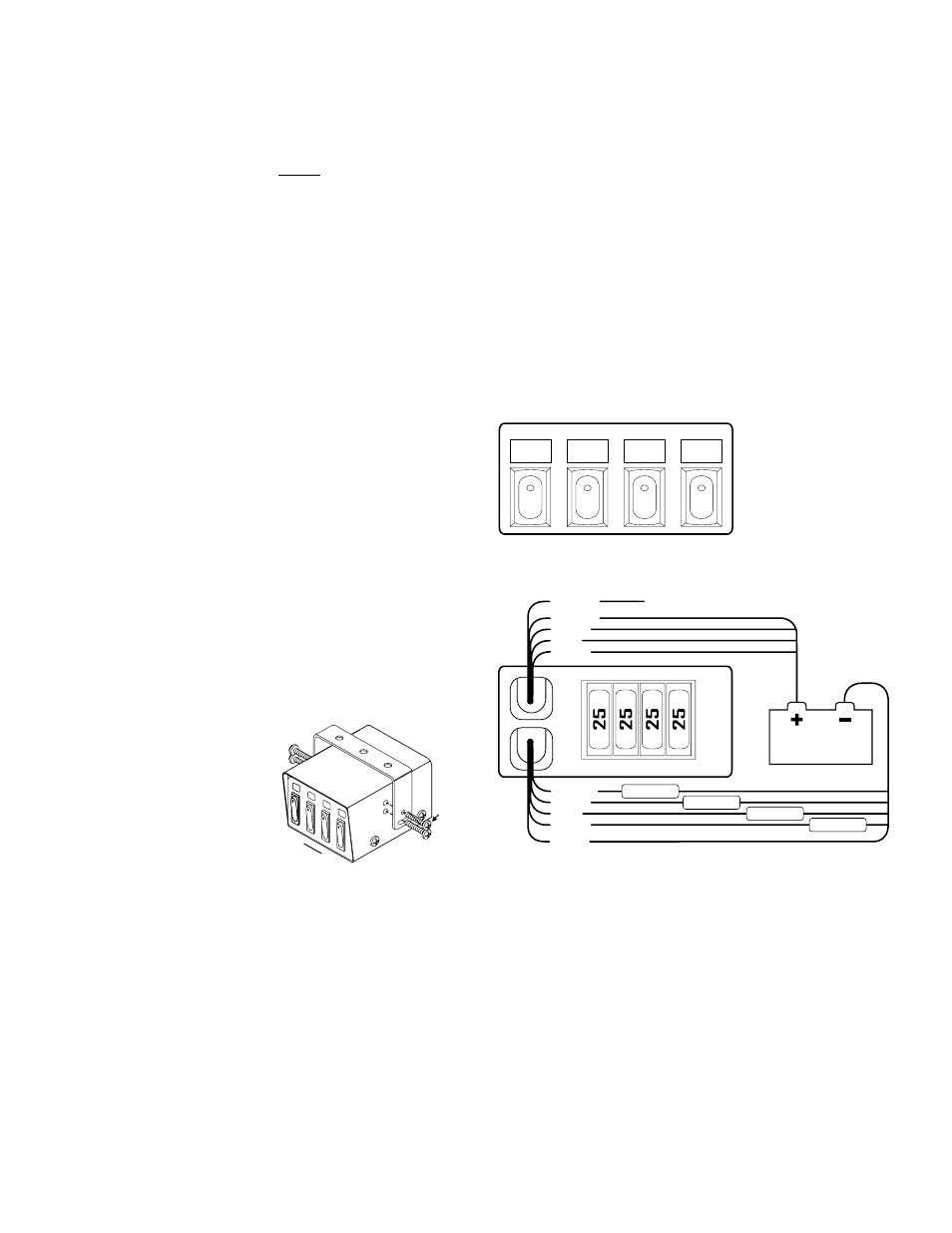
SW1:
yellow
wires
YELLOW
GREEN
BLUE
VIOLET
SW2:
green
wires
SW3
blue
wires
SW4
violet
wires
25 AMP FUSES
SW4
YELLOW
GREEN
BLUE
VIOLET
WHT/YEL
BLACK
BATTERY
Connect to +VBAT ignition controlled 100ma power source
FRONT
VIEW
REAR
VIEW
LOAD
LOAD
LOAD
LOAD
WIRING
DIAGRAM
SW3 SW2 SW1
Model PCC4W
WARNING! These switches are suitable for 25 amp, 12 volt DC
applications. Any attempt to load these switches above 25 amps will
result in switch failure.
WARNING! All customer supplied wires that connect to the positive
terminal of the battery must be sized to supply at least 125% of the
maximum operating current and be FUSED at the battery to carry
that load. DO NOT USE CIRCUIT BREAKERS WITH THIS PRODUCT!
Congratulations on selecting the PCC4W six switch power control center.
This product offers a unique and distinctive collection of features.
Features include:
•
Ignition controlled LED backlighting
•
Compact design
•
Switch 'active' LED indicators
•
Four 25 amp switches
•
72 switch function labels
Mounting:
An aftermarket center console is recommended for the mounting location
of the PCC4W. This not only allows the driver to reach the controls easily,
but also keeps the unit safely out of the path of the vehicle’s SRS air-bag.
Follow the console manufacturer’s instructions for mounting information. If
a console-type mount is not possible, the PCC4W includes a bail strap
mounting kit for over or under dash mounting.
WARNING: Regardless of the style selected, be sure to observe the
air-bag warning on the cover of this manual.
WARNING: Mounting this unit will require drilling. It is absolutely
necessary to make sure that no other vehicle components could be
damaged in the process. Check both sides of the mounting surface
before starting. If damage is likely, select a different location.
Bail Strap Mount:
1.
Position the bail strap in the selected mounting location. Using an
awl or other suitable tool, scribe the surface where the mounting
holes are to be drilled.
2.
Carefully drill the mounting
holes in the areas scribed
in step one. The size of the
drill bit should be
determined by the size of
the mounting hardware
(customer supplied) and
the thickness of the
mounting surface.
3.
Using the customer
supplied mounting
hardware, secure the bail strap to the mounting location.
Console Mount:
Console manufacturers offer mounting kits that include all the necessary
hardware and brackets required to mount this unit into their console. The
console mount brackets are secured onto the unit the same way the bail
bracket is. Refer to the manual included with your console.
Function Labels: Take the supplied label kit and determine which label
describes the function of switch 1. Peel the label off the backing and place
it in the label window above switch 1. Press the label lightly into place.
Repeat for each switch.
Wiring:
BLACK WIRE: This wire supplies ground to both the units function
window backlighting and the switch 'active' LED indicators located on the
front of each switch. This wire can be connected to any vehicle ground
that can supply 100ma.
WHITE/YELLOW WIRE: This wire supplies power to the units window
backlighting. This wire can be connected to any ignition controlled +VBAT
power source that can supply 100ma. NOTE: If your PCC4W does not
have a white/yellow wire, then it is not equipped with the
backlighting feature.
IMPORTANT: It is the responsibility of the installation technician to
make sure that the installation and operation of this product will not
interfere with or compromise the operation or efficiency of any vehi-
cle equipment! Before returning the vehicle to active service, visu-
ally confirm the proper operation of this product.
Screw
SW1
SW4
►