Important! read these warnings before continuing, Fig. 1 – Whelen HWLCC11 User Manual
Page 2
Page 2
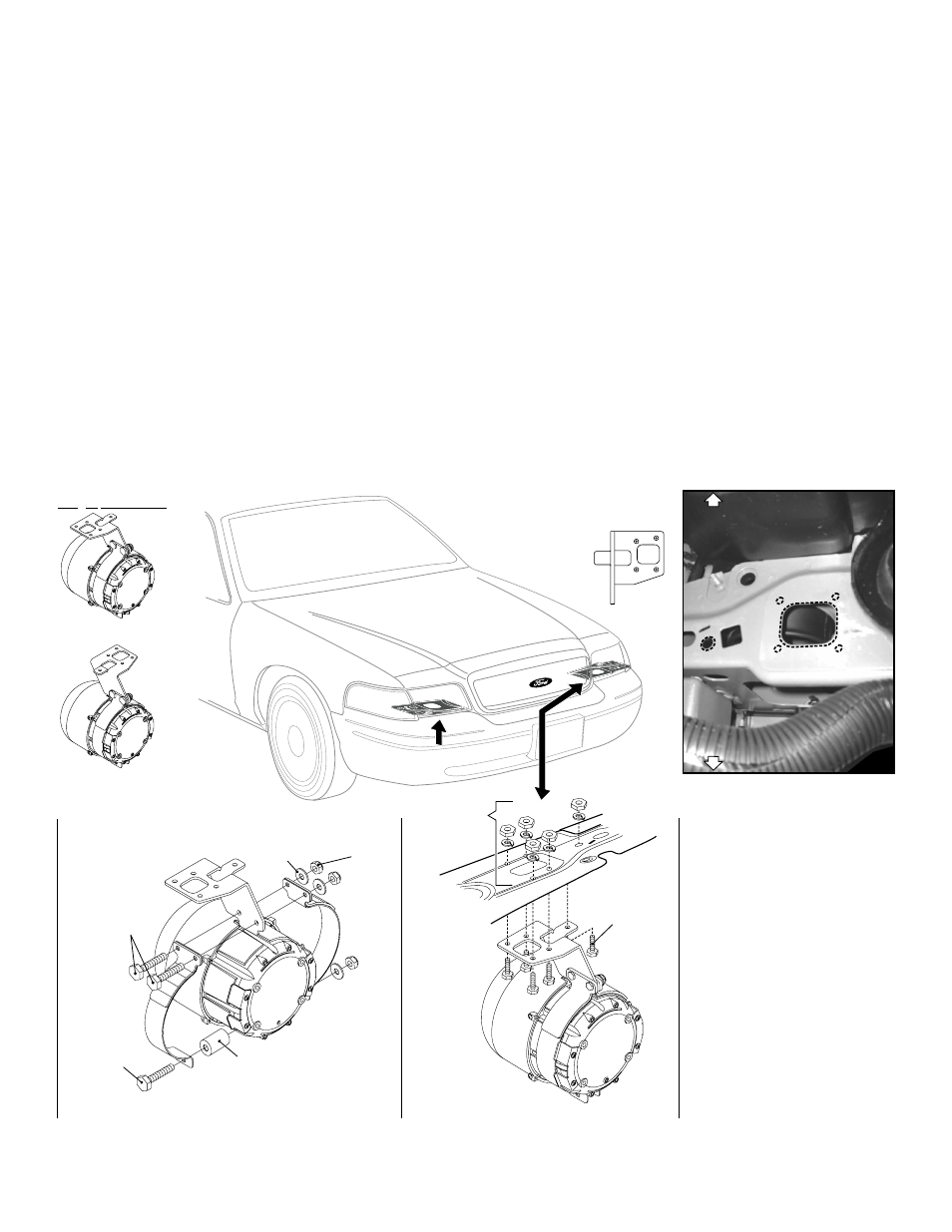
Driver side mounting location.
Mounting Bracket to Speaker
5/16-18 X 1"
Hex Head Bolt
(QTY 5)
FRONT OF VEHICLE
A
B
B
A
Driver and passenger
side mounting locations
Driver Side
Passenger Side
bracket
bracket
Locate mounting hardware and
bracket with these two holes
Fig. 1
CAUTION! Mounting the siren will
require drilling. It is absolutely
necessary to make sure that no
other vehicle components could
be damaged while drilling. If any
vehicle component could suffer
any potential harm, select a
different mounting location.
IMPORTANT: It is the responsibility
of the installation technician to
makesure that the installation and
operation of this product will not
interfere with or compromise the
operation or efficiency of any
vehicle equipment!
IMPORTANT! Before returning the
vehicle to active service, visually
confirm the proper operation of
this product, as well as all vehicle
components/equipment.
Pro er Orientation
p
REAR OF VEHICLE
REAR OF VEHICLE
REAR OF VEHICLE
Enlarged
view
of
Mounting
area
Mounting Speaker with Bracket to Vehicle
5/16 S
L
W
plit ock
asher (QTY 5)
5/16-18 Hex Nut
1/2" dia. (QTY 5)
5/16-18 X 1.5"
Hex HD Screw
5/16-18 X 1 Hex
Head Bolt SS
Spacer
5/16-18
Elastic
Stop Nut
(3 places)
5/16 Flat Washer
(3 places)
Installation:
1.
Secure the siren speaker to the mounting bracket using the supplied
hardware as shown below. Make sure you mount the bracket
correctly for the side of the vehicle you are mounting to (see “Proper
Orientation”). IMPORTANT: Be careful not to over tighten the
strap bolt.
2.
Find the mounting location (see below). The speaker mounts to the
underside of the vehicle, a little behind the headlight forward of the
front tire. NOTE: There may be a snap-on cover over the
mounting area on some vehicles. Remove before installation.
Hold the bracket up to the mounting area. Orient the bracket using
the 2 holes in the mounting surface (A & B) indicated below (Fig. 1).
3.
With the bracket in place, mark the 4 mounting holes off onto the
mounting surface.
4.
Remove bracket and drill the 4 mounting holes with a 5/16” drill bit.
The fifth mounting hole (B) is already present on the vehicle.
5.
Secure the siren speaker to the vehicle using the supplied mounting
hardware. IMPORTANT! The slotted holes in the siren speaker
must face down toward the road after mounting so that water
will not be trapped inside.
6.
Extend the WHITE / Positive (+) and BLACK Negative (-) speaker
wires to your siren amplifier and connect using the amplifiers
instructions.
IMPORTANT! READ THESE WARNINGS BEFORE CONTINUING!
The Howler™ Supplemental Siren was designed for use in high-risk areas such as an intersection. It is not intended to be, nor should be
operated as a replacement or alternative to the vehicle’s primary siren.
The low-frequency tones of the Howler™ demonstrate significantly different audio characteristics as compared to those of a traditional higher-
frequency siren. While the low-frequency tones are better able to penetrate other vehicles, thus alerting drivers to the presence of the
responding emergency vehicle, these tones may also penetrate into the responding vehicle itself. This could potentially expose the operator to
increased noise levels.
To help eliminate overexposure, the Howler™ siren has been designed with a built-in timing circuit. The Occupational Safety & Health
Administration (OSHA) (www.osha.gov) provides information necessary to determine safe exposure times in Noise and Hearing Conservation,
Section 1910.95 (Occupational Noise Exposure). Until you have determined the safe exposure times for your specific application, this siren
should be configured for the minimum operating time and operators should be required to use an approved hearing protection device.
FAILURE TO FOLLOW THIS RECOMMENDATION COULD CAUSE HEARING LOSS!