Important! read these warnings before continuing, Fig. 3 fig. 5, Fig. 1 – Whelen HWLRB7 User Manual
Page 2: Fig. 2, Fig. 4, Installation: front of vehicle, Installation: rear of vehicle, Page 2
Page 2
5/16 - 18 X 1-1/4
HEX HEAD BOLT
Front of
Vehicle
RAISED
A R E A
RAISED
A R E A
RAISED
A R E A
Fig. 2
5/16 SPLIT LOCK WASHER
5/16 - 18 X 1 HEX HD BOLT
5/16 - 18
ELASTIC
STOP NUT
5/16" FLAT
WASHER
5/16 - 18 X 1-1/4
HEX HD BOLT
5/16 - 18 X 1-3/4
HEX HD BOLT
5/16" ELASTIC
S T O P N U T
5/16 FLAT
WASHER
5/16" ELASTIC
S T O P N U T
5/16 FLAT
WASHER
SPACER
Fig. 3
Fig. 5
Mount
to
riv
nuts
on
vehicle
BRACKET
Slides between
mounting
strap
ends.
5/16-18 X 1-1/4
Hex Head
Screw SS
1-1/4 - 20 X 1
H E X H D
S C R E W
5/16 FLAT
WASHER
5/16 INTERNAL
TOOTH LOCK
W A S H E R
5/16-18 X
1-3/4 Hex Head
Screw SS
5/16 Flat
Washer
SPACER
5/16-18
Elastic
Stop Nut
Mounting
Location
RAISED AREA
FRAME
ROAD
View of the vehicle looking up from the road.
Fig. 1
Fig. 1
Front of Vehicle
Fig. 1
Fig. 4
Fig. 4
Fig. 4
Bottom view. Rear of vehicle looking up from the road.
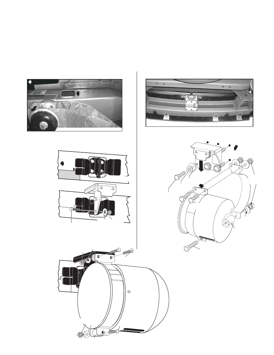
Installation: Front of Vehicle
1.
Remove the gravel shield from the vehicle and set it aside.
2.
Locate the mounting area. The speaker will mount on the driver side to a hole
in the frame toward the front of the vehicle (Fig. 1).
3.
Secure mounting
clamp to vehicle
using the front and
rear brackets. There
is a raised area on
the frame, near the
mounting hole. The
front bracket goes on
this side. One of the
forks on the bracket
rests on the raised
area (Fig. 2).
4.
Secure the mounting
bracket to the
assembled front and
rear brackets (Fig. 3).
5.
Secure the two
mounting straps to the
mounting bracket.
Tighten the parts snugly, but do not tighten all the way (Fig. 3).
6.
Slide the siren speaker into the mounting strap and insert the mounting bolt
and spacer into the
bottom strap hole to
hold the speaker in
place while you add
the bottom mounting
hardware. Firmly
tighten all of the
hardware (Fig. 3).
IMPORTANT: The
slotted holes in the
speaker must face
the road after
mounting for
drainage.
7.
Extend the BLACK (-) negative and
WHITE (+) positive speaker wires to
your siren amplifier and follow
amplifier instructions.
8.
Reinstall the gravel shield
removed in step 1 to complete the
installation.
Installation: Rear of Vehicle
1.
Place the mounting bracket in its exact mounting position and mark off the 6
mounting holes (Fig. 4).
IMPORTANT NOTE!
This installation uses
Rivnuts™ to secure the
bracket to the vehicle.
This type of hardware
requires the use of a
specialized installation
tool. Refer to the
owners manual
included with this
tool for proper
installation. Be
sure to follow
mounting hole
specifications
precisely!
2.
Drill the mounting
holes with a .391
drill bit and secure
the bracket with
the 6 supplied riv
nuts.
3.
Secure mounting
strap to speaker and
speaker to mounting
bracket. Tighten all
hardware securely
(Fig. 5).
IMPORTANT: The slotted holes in the speaker must face the road for drainage.
4.
Extend the BLACK (-) negative and WHITE (+) positive
speaker wires to your siren amplifier. Follow the amplifier
instructions for connections.
IMPORTANT: It is the responsibility of the installation
technician to make sure that the installation and
operation of this product will not interfere with or
compromise the operation or efficiency of any vehicle
equipment!
IMPORTANT! Before returning the vehicle to active
service, confirm the proper operation of this product, as
well as all vehicle components/equipment.
IMPORTANT! READ THESE WARNINGS BEFORE CONTINUING!
The Howler™ Supplemental Siren was designed for use in high-risk areas such as an intersection. It is not intended to be, nor should be operated as, a
replacement or alternative to the vehicle’s primary siren.
The low-frequency tones of the Howler™ demonstrate significantly different audio characteristics as compared to those of a traditional higher-frequency
siren. While the low-frequency tones are better able to penetrate other vehicles, thus alerting drivers to the presence of the responding emergency
vehicle, these tones may also penetrate into the responding vehicle itself. This could potentially expose the operator to increased noise levels.
To help eliminate overexposure, the Howler™ siren has been designed with a built-in timing circuit. The Occupational Safety & Health Administration
(OSHA) (www.osha.gov) provides information necessary to determine safe exposure times in Noise and Hearing Conservation, Section 1910.95
(Occupational Noise Exposure). Until you have determined the safe exposure times for your specific application, this siren should be configured for the
minimum operating time and operators should be required to use an approved hearing protection device. FAILURE TO FOLLOW THIS
RECOMMENDATION COULD CAUSE HEARING LOSS!