Whelen CANEM16 User Manual
Page 2
Page 2
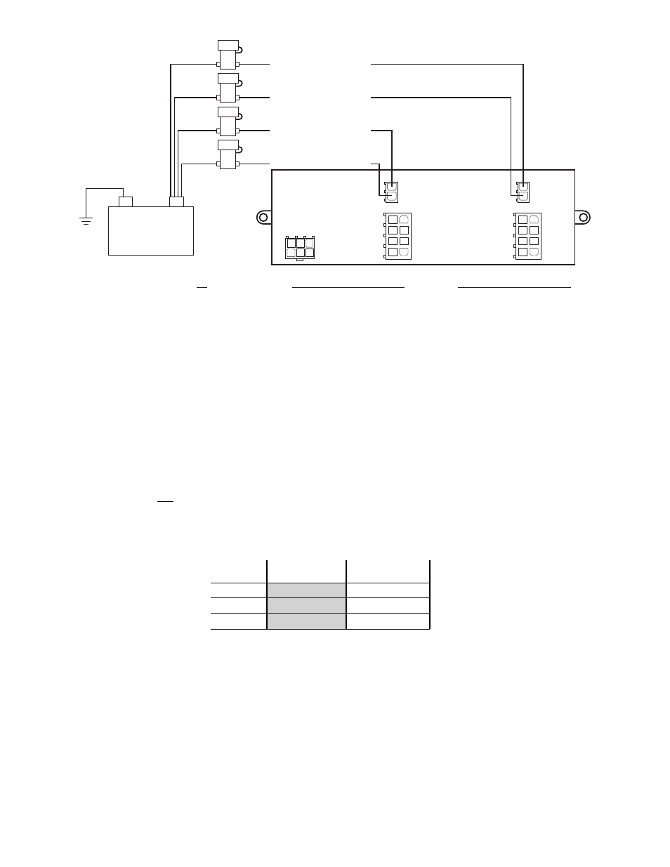
J2 Outputs 5 - 8
J3 Outputs 5 - 8
J2 Outputs 1 - 4
Using appropriately
sized wire, extend
the input wires to
fuse blocks installed
at the battery.
Connect each fuse
block individually
to the Pos. (+)
battery terminal.
Each input wire
must be fused
independently.
J3 Outputs 1 - 4
J2 (2.5A MAX per outlet)
1 - Output 9
2 - Output 10
3 - Output 11
4 - Output 12
5 - Output 13
6 - Output 14
7 - Output 15
8 - Output 16
J3 (2.5A MAX per outlet)
1 - Output 1
2 - Output 2
3 - Output 3
4 - Output 4
5 - Output 5
6 - Output 6
7 - Output 7
8 - Output 8
J2
J3
J1
J1
1 - Not Used
2 -
3 - Black (Ground)
4 - Green (CAN A)
5 -
6 - Grey (CAN B)
1
4
2
5
3
6
(10A)
(10A)
(10A)
(10A)
1
5
2
6
3
7
4
8
1
5
2
6
3
7
4
8
(+)
Battery
(-)
5 Amps
10 Amps
18 AWG
16 AWG
14 AWG
15 Feet
7.5 Feet
24 Feet
12 Feet
39 Feet
19.5 Feet
Wire
Gauge
Current Draw
Wire Gauge Calculation Chart
To use this chart...
1. Determine the amount of current being drawn through the wire. Locate this
number in the top row. If the current value is between adjacent values, use the
higher number.
2. Follow this column down until the length of the installed wire is shown. If the exact
length is between adjacent values, use the higher number. The wire gauge shown
for this row represents the minimum size wire that should be used.
IMPORTANT! This product was designed to be configured using the WeCan system programming software. It can not
be used as a stand alone module.
WARNING! All customer supplied wires that connect to the positive terminal of the battery must be sized to supply at
least 125% of the maximum operating current and fused ‘at the battery to carry that load. DO NOT USE CIRCUIT
BREAKERS WITH THIS PRODUCT!
Addressing - The network address for this module is pre-configured to be identified in the configuration software as
“MODULE 1”. If two (2) REMOTE16 modules are installed, it will be necessary to cut the jumper wire located between
J1-2 and J1-5, on one of the modules. That module will now be identified in the configuration software as “MODULE 2”.