Whelen CANTEMPB User Manual
Automotive: cant rol, Installation guide: cantrol™ temperature sensor
Page 1
®
ENGINEERING COMPANY INC.
Automotive:
CanT
rol™
Installation Guide:
CanTrol™ Temperature Sensor
©2010 Whelen Engineering Company Inc.
Form No.14437 (111810)
51 Winthrop Road
Chester, Connecticut 06412-0684
Phone: (860) 526-9504
Fax: (860) 526-4078
Internet: www.whelen.com
Sales e-mail: [email protected]
Canadian Sales e-mail: [email protected]
Customer Service e-mail: [email protected]
For warranty information regarding this product, visit www.whelen.com/warranty
Degrees °F
Voltage Out
0 .........................2.5
10 .........................2.8
20 .........................3.1
30 .........................3.5
40 .........................3.9
50 .........................4.2
60 .........................4.6
70 .........................5.0
80 .........................5.3
90 .........................5.7
100 .........................6.0
110 .........................6.4
120 .........................6.8
130 .........................7.1
140 .........................7.5
150 .........................7.9
160 .........................8.2
170 .........................8.6
180 .........................9.0
WARNING! Permanent mounting of this product will require drilling. It is absolutely necessary to make sure that no other vehicle
components could be damaged by this process. Check both sides of the mounting surface before starting. If damage is likely, select
a different mounting location.
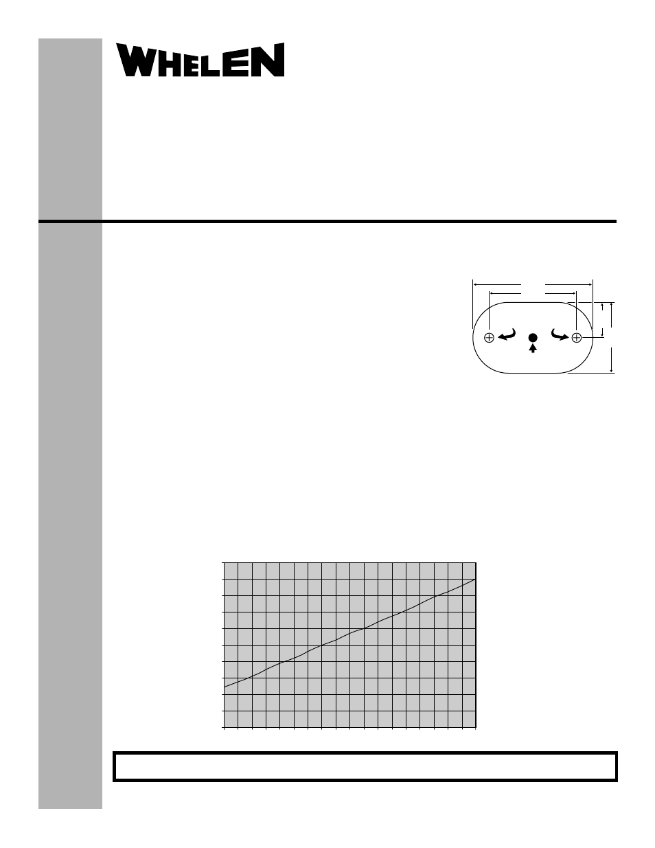
.915"
.457"
1.550"
1.130"
Mounting Hole for
heet etal crew
#6 S
M
S
3/8” WIRE
HOLE
Mounting and connections...
1.
Place the flange onto the mounting surface and mark the location for the two mounting
screws and the wire access hole location as shown. NOTE: There is an optional wire exit
hole on the bottom of the flange if you prefer the wires to exit the bottom of the sensor. Be
sure the installation will not interfere with anything behind the mounting surface.
2.
Drill two pilot holes for the two #6 X 3/8" sheet metal mounting screws and a 3/8” wire access
hole. Be sure to thoroughly deburr this hole.
3.
Route the wires through the gasket and the wire access hole and secure the lighthead with
the supplied mounting screws. NOTE: Make sure the Whelen logo on the lens is oriented
correctly after mounting.
4.
Connect the sensor wires as follows:
RED -
Connect to an ignition controlled +12.8VDC power source
BLACK -
Connect to Chassis Ground
WHT/BLK - Connect to the first available Analog Input on CanTrol
(for example: Analog 1)
In order to operate correctly, the appropriate analog input must be properly configured using the
CanTrol programming software. The following values are presented as a starting point. Individual
applications may require different values than those shown here.
Update = Select the minimum value (20 ms.)
Average = Select the minimum value (1)
Upper Trip Point = Select a starting value of 5.3V (see graph for details)
Lower Trip Point = Select a starting value of 5.0V (see graph for details)
IMPORTANT! Before returning this vehicle to active service, confirm proper operation of
this product, as well as all vehicle components/equipment.
Analog Voltage vs Temperature
0.00
1.00
2.00
3.00
4.00
5.00
6.00
7.00
8.00
9.00
10.00
0 10 20 30 40 50 60 70 80 90 100 110 120 130 140 150 160 170 180