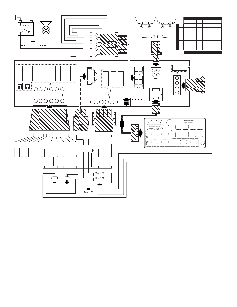
Wiring, Battery, Siren input (j7) - red: power - black: ground – Whelen 295SDA1 User Manual
Page 3: Speaker (j6) - org, yel, gry & brn, Horn relay (j5) - white & grey, Radio rebroadcast (j5) (optional) - two blue wires
Page 3
11
9
7
5
3
1
12
10
8
6
4
2
1
2
3
4
8&6 1&3
5
3
1
2
7
9
11
12
10
2
1
AUX-
A
OUTPUT / Normally Closed
AUX-A
OUTPUT / Normally Open
AUX-A
INPUT
AUX-B OUTPUT / Normally Closed
AUX-B OUTPUT / Normally Open
AUX-B INPUT
20 AMP FUSE
4
1
2
3
4
5
6
7
8
9
10
3
1
2
#2
#1
UNIT ENABLE (+)
SIREN DISABLE (-)
(See Radio Rebroadcast)
RADIO
(See Radio Rebroadcast)
RADIO
CONTROL
HEAD
295SDA1
CONTROL HEAD CABLE
SIREN "IN USE" ICON DRIVER
SIREN DISABLE (+)
AUX INPUT (-)
BACKLIGHT (+)
SPEAKER
SPEAKER
HORN RELA
Y
+12V
To Horn
Button
1
2
3
4
10
AMP
FUSE
10
AMP
FUSE
10
AMP
FUSE
10
AMP
FUSE
10
AMP
FUSE
10
AMP
FUSE
J3
1
2
3
4
1
6
2
7
4
9
5 10
3
8
J7
1
2
3
4
20
AMP
FUSE
20
AMP
FUSE
20
AMP
FUSE
2
1
4
3
2
1
J4
J4
J5
J6
J5
J7-1
J6
J2
J7
LOAD
LOAD
LOAD
To
2 wire T
A
BATTERY
BATTERY
VEHICLE
HORN
RED/BLK
GR
Y
ORG
BRN
YEL
GRY
WHT/ORG
BLU
BLU
WHT
WHT/VIO
VIO
WHT/GRN
GRN
RED
WHT/YEL
RED
WHT/YEL
WHT/BLU
WHT/ORG
WHT/BRN
GRN
WHT/RED
BLU
YEL
ORG
BRN
RED
WHT/GRN
WHT
BLU
GRN
RED
BLK
BLK
LOAD
40 AMP FUSE
20 AMP FUSE
40 AMP FUSE
LOAD
LOAD
LOAD
LOAD
LOAD
RED
CUT WIRE
SIREN POWER
SIREN POWER
SIREN POWER
J1
OUTPUTS
J1
OUTPUTS
J2
OUTPUTS
J2
OUTPUTS
J1
OUTPUTS
J2
OUTPUTS
J5
CONTROL
WIRES
J5
CONTROL
WIRES
POWER
POWER
J5
CONTROL
WIRES
POWER FUSE
THESE FUSES ARE CUSTOMER SUPPLIED
PROGRAMMING
DIP SWITCHES
1
ON
OFF
2 3 4
SPKR
SPKR
4
2
J1
10
AMP
FUSE
10
AMP
FUSE
11
9
7
5
3
1
12 10
8
6
4
2
J4
J4
INS = Insufficient
INS
INS
INS
INS INS
12
6
4
3
19.5
9.5
6.5
5
4
3
3
31
15.5
10.5
7.5
6
5
4.5
4
49
24.5
16.5
12.5
10
8
7
6
78
39
26
19.5
15.5
13
11
10
124
62
41.5
31
25
20.5
17.5
15.5
10
20
30
40
50
60
70
80
Current Draw /
AMPS
16
14
12
10
8
6
Wire Gage / AWG
Wire Length / Feet
Wiring:
WARNING: All customer supplied wires that connect to the positive
terminal of the battery must be sized to supply at least 125% of the
maximum operating current and FUSED at the battery to carry that
load. DO NOT USE CIRCUIT BREAKERS WITH THIS PRODUCT!
Siren Input (J7) - RED: Power - BLACK: Ground
1.
Splice the 2 RED (Power) wires together, then extend this single
RED wire toward the vehicle battery. Splice the 2 BLACK (Ground)
wires together and extend this single BLACK wire toward the vehicle
battery. To pass the RED and BLACK wires through, you may have to
drill a hole in the firewall. Insert a grommet to protect the wires.
2.
Route the RED and BLACK wires along the factory harness towards
the battery and install a fuse block (user supplied) on the end of the
RED wire. Remove fuse from fuse block before connecting any
wires to battery.
3.
Connect fuse block wire to POSITIVE terminal on battery. There
must not be more than 2 feet of wire between fuse block and battery.
The wire between the fuse and battery is “unprotected”, do not
allow it to chafe and short to ground. Connect the BLACK wire to the
factory chassis ground.
Speaker (J6) - ORG, YEL, GRY & BRN
1.
Route the ORG, YEL, GRY and BRN wires toward the vehicle
siren speakers, along the factory wire harness and through the
firewall at the same point as the RED and BLACK wires.
2.
Connect the YELLOW wire to the POSITIVE terminal on
SPEAKER #1 and the ORANGE wire to the POSITIVE
terminal on SPEAKER #2. NOTE: For single speaker
installs use the YELLOW wire and cap the ORANGE wire.
3.
Connect BRN wire to NEGATIVE connection on speaker #1.
4.
Connect GREY wire to NEGATIVE connection on speaker #2.
Horn Relay (J5) - WHITE & GREY
1.
Route WHITE and GREY wires along factory wire harness and
through the firewall at the same point as the RED and BLACK wires.
2.
Route WHITE and GREY wires to vehicle’s horn relay. If possible,
follow the factory wire harness to this relay.
3.
Cut the wire that connects the vehicle horn to the horn relay.
4.
Connect the WHITE wire to the wire coming from the horn relay.
5.
Connect the GREY wire to the wire coming from the horn.
Radio Rebroadcast (J5) (optional) - Two BLUE wires
The two remaining BLUE wires are used to connect your two-way
radio’s external speaker for radio rebroadcast (optional connection).
Note: If your remote speaker is amplified (speaker has a power amp
circuit), radio rebroadcast will not work and should not be used.
1.
Locate the 2 wires that connect the external speaker to the 2-way
radio, cut one and splice one of the BLUE wires into this circuit.
2.
Cut the remaining speaker wire and splice the other BLUE wire into
this circuit.