Mounting, Wiring, Front panel – Whelen EPSL1 User Manual
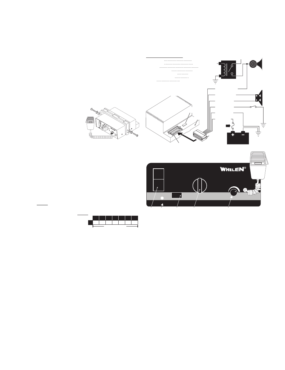
Page 2: Page 2, Bail strap mount, Console mount, Microphone clip, Siren input connector - red: power - black: ground, Yellow & brown - speaker wires, White/green - horn relay wires
Page 2
STDBY
POWER
MAN1
MAN2
HF
T1
T2
VOL
T3
MAN
SPKR
Power
Switch
Manual
Button
Rotary
Switch
Diagnostic
Indicator
Microphone
Volume
20 18 16 14 12
5 7.5 12 19.5 31
10
22
3
Wire Gauge / AWG
TABLE 1
Current Draw
AMPS
Distance in Feet
10
49
Mounting:
This siren is designed to be mounted directly onto the dash or other surface through
the use of a bail strap mounting bracket. The unit may also be mounted into your
vehicle’s console (if so equipped).
WARNING: Regardless of the style selected, be sure to observe the Air Bag
Warning on the cover of this manual.
WARNING: Mounting this unit will require drilling. It is absolutely necessary to
make sure that no other vehicle components could be damaged in the process.
Check both sides of the mounting surface before starting. If damage is likely,
select a different location.
Bail Strap Mount:
1. Position bail strap in selected mounting
location and drill mounting holes, then
secure the bail strap to the vehicle.
2. Secure the siren to the bail strap as shown.
Tighten the screws firmly.
Console Mount:
Console manufacturers offer mounting kits that include all the necessary hardware
and brackets required to mount this unit into their console. The console mount
brackets are secured onto the unit the same way as the bail bracket. Please refer to
the manual included with your console.
Microphone Clip:
A microphone clip is included. Secure with provided hardware.
WARNING: Refer to the Air Bag Warning before installing this clip.
Wiring:
Siren Input Connector - RED: Power - BLACK: Ground
WARNING: All customer supplied wires that connect to the positive terminal of
the battery must be sized to supply at least 125% of the maximum operating
current and FUSED at the battery to carry that load. DO NOT USE CIRCUIT
BREAKERS WITH THIS PRODUCT!
1. Extend the RED and BLACK wires
toward the vehicle battery. To pass
the RED and BLACK wires
through, you may have to drill a
hole in the firewall. Insert a grommet to protect the wires.
2. Route the RED and BLACK wires along the factory harness towards the battery
and install a fuse block (user supplied) on the end of the RED wire. Remove fuse
from fuse block before connecting any wires to battery.
3. Connect fuse block wire to POSITIVE terminal on battery. There must not be more
than 2 feet of wire between fuse block and battery. The wire between the fuse and
battery is “unprotected,” do not allow it to chafe and short to ground.
4. Connect the BLACK wire to the factory chassis ground.
YELLOW & BROWN - Speaker Wires
1. Route the YELLOW and BROWN wires toward vehicle siren speakers, along
factory wire harness and through firewall at the same point as the RED and
BLACK wires.
2. Connect the YELLOW wire to the POSITIVE terminal on the SPEAKER and the
BROWN wire to NEGATIVE connection on the speaker.
WHITE/GREEN - Horn Relay Wires:
1. Route WHITE/GREEN wire along factory wire harness and through firewall at the
same point as the RED and BLACK wires.
2. Route WHITE/GREEN wires to vehicle’s horn relay. If possible, follow the factory
wire harness to this relay.
3. Locate the wire that connects the vehicle horn to the horn relay.
4. Connect the WHITE/GREEN wire to the wire that runs from the horn relay to the
horn.
GREEN - Aux Override:
This wire is activated by switching it to ground (see page 3 for operation).
• Speaker diagnostic indicator
• 100 watts of output power
• Scan-Lock™ siren tone programming
• Hands-Free operation
• LED Backlighting
• 7 position rotary switch function selector
• Compact design
• Harmonically rich composite air horn tones
• Title 13 compliant profiles
• Non-destructive short circuit protection.
• Horn ring control inputs
• PA Override
Congratulations on selecting the Epsilon™ Siren. This siren offers a unique and distinctive collection of features designed to allow the
user to customize the operation of this siren to suit their individual needs. Features include:
®
16 Position
Connector
WIRING DIAGRAM
Fuses & Fuse Blocks are customer supplied.
1
FUSE
0 AMP
CHASSIS
GROUND
A U X I L I A R Y
O V E R R I D E
CONNECTION
(OPTIONAL)
100W
SPEAKER
HORN
RELAY +12V
TO
HORN
BUTT
ON
BATTERY
VEHICLE
HORN
INPUT VOLTAGE
INPUT CURRENT
INPUT FUSE
SPEAKER IMPEDANCE
OPERATING TEMPERATURE
STORAGE TEMPERATURE
HUMIDITY
OUTPUT VOLTAGE
OUTPUT POWER
16 Position
Outlet
Rear
view
of
amplifier
12.8 VDC ±20%
8 AMPS MAX.
10 AMPS
11 OHMS MIN.
-30° C. TO +60° C.
-40° C. TO +70° C.
99% (NON CONDENSING)
@ 15 VDC @ 11 OHMS 34 V RMS MAX.
@ 15 VDC @ 11 OHMS 105 WATTS MAX.
Scan-Lock™
10 Amp
F u s e
Unused Outlets: 2 - 3 - 5 - 7 - 8 - 9 - 10
13 - 14 & 16
Unused Outlets:
WHT/GRN
YELLOW
BROWN
GREEN
BLACK
RED
15
11
6
4
12
1
Power Switch
This switch has two positions. Down (Off) and Up (On). When this switch is off, siren
functions are disabled.
Rotary Switch
The Rotary Knob controls the siren functions of the Epsilon. There are 7 positions
that may be selected (see “Switch Operations”).
Volume Knob
The Volume Knob controls the volume of Public Address function. Volume is
increased by rotating the knob in a clockwise direction. Rotating the volume knob in a
counter-clockwise direction decreases the volume produced by these features. The
volume knob has no effect on siren tones.
MAN Button
The Manual button generates a variety of tones, depending on what position the
rotary knob is in (see “Switch Operations”).
Diagnostic Indicator:
While this siren is under normal use the diagnostic indicator is used to indicate fault
conditions with your siren system. The following table lists the type of fault and the
indicators response. If the indicator is on steady while a tone is in use, this implies
that there is no fault with the speaker output.
Fault Condition Diagnostic Indicators Response
Speaker Short Circuit: The speaker LED will be in a SingleFlash mode (the LED will
be on and off an equal amount of time) and siren tones won’t operate.
Speaker Undercurrent: Speaker LED will be off. All tones will continue to operate.
Microphone:
Whenever the siren is on, activating the microphone (pressing the switch on the side
of the mic.) will shut down any other siren functions and enable public address
operation regardless of the rotary switch position or any other switch or input.
Front Panel