Mounting, Wiring, Page 2 vo l 5 6 – Whelen EPSL2S6 User Manual
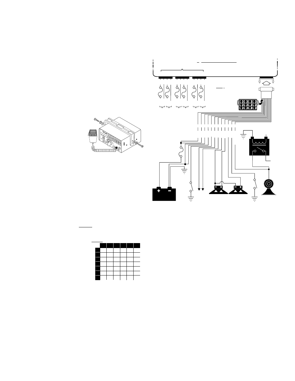
Page 2: Bail-strap mount, Console mount, Microphone clip, Siren input connector - red: power - black: ground, Yellow, orange & brown - speaker wires, White/green - horn ring wires, Green - aux override
Page 2
VO
L
5
6
Mounting:
This siren is designed to be mounted directly onto the dash or other
surface through the use of a bail-strap mounting bracket. The unit may
also be mounted into your vehicle’s console (if so equipped).
WARNING: Regardless of the style selected, be sure to observe the
air-bag warning on the cover of this manual.
WARNING: Mounting this unit will require drilling. It is absolutely
necessary to make sure that no other vehicle components could be
damaged in the process. Check both sides of the mounting surface
before starting. If damage is likely, select a different location.
Bail-strap mount:
1. Position bail strap in selected
mounting location and drill mounting
holes, then secure the bail strap to
the vehicle.
2. Secure the siren to the bail strap as
shown. Tighten the screws firmly.
Console Mount:
Console manufacturers offer mounting kits that include all the necessary
hardware and brackets required to mount this unit into their console. The
console mount brackets are secured onto the unit the same way the bail
bracket is. Please refer to the manual included with your console.
Microphone Clip:
A microphone clip is included. Secure with provided hardware.
WARNING: Refer to the Air Bag Warning before installing this clip.
Wiring:
Siren Input Connector - RED: Power - BLACK: Ground
WARNING: All customer supplied wires that connect to the positive
terminal of the battery must be sized to supply at least 125% of the
maximum operating current and FUSED at the battery to carry that
load. DO NOT USE CIRCUIT BREAKERS WITH THIS PRODUCT!
1. Extend the RED and BLACK wires
toward the vehicle battery. To pass the
RED and BLACK wires through, you
may have to drill a hole in the firewall.
Insert a grommet to protect the wires.
2. Route the RED and BLACK wires
along the factory harness towards the
battery and install a fuse block (user
supplied) on the end of the RED wire.
Remove fuse before connecting any
wires to battery.
3. Connect fuse block wire to POSITIVE terminal on battery. There must
not be more than 2 feet of wire between fuse block and battery. The
wire between the fuse and battery is “unprotected”, do not allow it to
chafe and short to ground.
4. Connect the BLACK wires to the factory chassis ground.
YELLOW, ORANGE & BROWN - Speaker Wires
1. Route the YELLOW, ORANGE and BROWN wires toward vehicle siren
speakers, along factory wire harness and through firewall at the same
point as the RED and BLACK wires.
2. Connect the YELLOW wire to the POSITIVE terminal on SPEAKER #1
Connect the ORANGE wire to the positive terminal on speaker #2 and
the BROWN wire to NEGATIVE connection on both speakers.
WHITE/GREEN - Horn Ring Wires:
1. Route WHITE/GREEN wire along factory wire harness and through
firewall at the same point as the RED and BLACK wires.
2. Route WHITE/GREEN wires to vehicle’s horn relay. If possible, follow
the factory wire harness to this relay.
3. Locate the wire that connects the vehicle horn to the horn relay.
4. Connect the WHITE/GREEN wire to the wire that runs from the horn
relay to the horn.
GREEN - Aux Override:
This wire is activated by switching it to ground (See Page 3 for operation).
VIOLET - Siren Interruption:
Grounding the VIOLET wire will deactivate the siren. Removing ground
from the VIOLET wire will not reactivate the siren. The operator must reset
the siren by placing the rotary switch into one of the standby positions (HF,
MAN1, MAN2).
Two BLUE wires - Radio Re-Broadcast (optional):
The 2 remaining blue wires are used to connect your 2-way radio’s
external speaker for radio re-broadcast (optional connection).
NOTE: If your remote speaker is amplified (speaker has power amp
circuit), radio re-broadcast will not work and should not be used.
1. Locate the 2 wires that connect the external speaker to the 2-way radio,
cut one of them and splice one of the blue wires into this circuit.
2. Cut the remaining speaker wire and splice the other BLUE wire into this
circuit.
• Speaker diagnostic indicator
• 200 watts of output power
• Scan-Lock™ siren tone programming
• Hands Free operation
• 6 Lighting control outlets
• LED Backlighting
• 7 position rotary switch function selector
• Compact design
• Harmonically rich composite air horn tones
• Title 13 compliant profiles
• Non-destructive short circuit protection.
• Horn ring control inputs
• PA Override
Congratulations on selecting the Epsilon™ 2S6 Siren. This siren offers a unique and distinctive collection of features designed to
allow the user to customize the operation of this siren to suit their individual needs. Features include:
16.5
12.5
10
8
7
26
19.5
15.5
13
11
41.5
31
25
20.5
17.5
66
49.5
39.5
33
28
104
78.5
63
52.5
45
6
10 15.5 24.5 39
30
40
50
60
70
10
8
6
4
2
80
24.5 39 62 98.5 157
20
10.5
7.5
6
5
4.5
4
12
15.5
Wire Gauge / AWG
TABLE 1
Current
Draw
/AMPS
Distance
is
shown
in
feet.
12 Position
Connector
(Rear View)
Outputs
Outputs
HORN
RELA
Y
+12V
VEHICLE
HORN
100 WATT
SPEAKER
100WATT
SPEAKER
TO 2-WAY
RADIO
SPEAKER
TO HORN
BUTTON
NOTE:
Do
use circuit breakers
with this product.
All Fuses & Fuse Blocks
are supplied by the customer.
NOT
1 4 2 5 9 6 3 7 8 12 10 11
SIREN
INTERRUPT
(Optional)
CHASSIS
GROUND
3
2
1
6
5
4
9
8
7
12
11
10
BATTERY
Epsilon™ 2S6 Siren
Fuse
@
20
AMP
S
(12V
)
FUSE AS REQUIRED
BRN VIO BLU WHT
BRN VIO BLU WHT
LOAD
POWER
LOAD
POWER
LOAD
POWER
LOAD
POWER
WHT/GRN
GRN
BLU
BLU
VIO
BLK
BLK
RED
RED
YEL
ORG
BRN
SW2 SW1
SW4 SW3
Outputs
BRN VIO BLU WHT
LOAD
POWER
LOAD
POWER
SW6 SW5