Front panel, Wiring, Mounting – Whelen GAMMA2 User Manual
Page 2: Operation
Page 2
TABLE 1
Distance in Feet
INS = Insufficient
18
31
15.5
10.5
7.5
16
49
24.5
16.5
12.5
14
78
39
26
19.5
12
10
8
10
20
30
40
Wire Gage / AWG
INS.
INS.
7.5
4
12
6
4
3
19.5
9.5
6.5
5
Current
Draw
(AMPS
)
Split Lock
Washer
Screw
Ext. Tooth
Lock Washer
LED 1
Indicators:
LED 2
LED 3
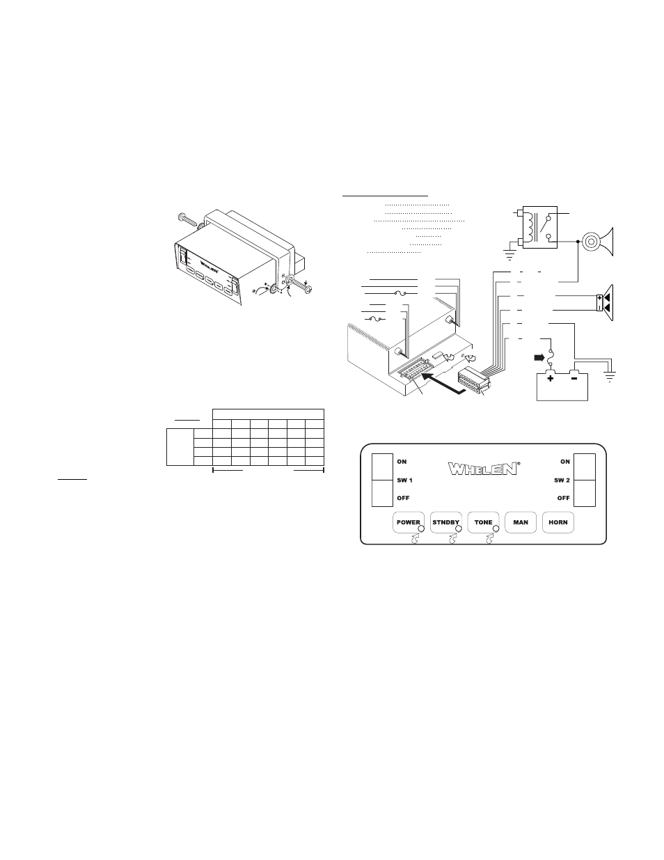
Front Panel
Mounting:
This siren is designed to be mounted directly onto the dash or other
surface through the use of a bail-strap mounting bracket. The unit may
also be mounted into your vehicle’s console (if so equipped).
WARNING: Mounting this unit will require drilling. It is absolutely
necessary to make sure that no other vehicle components could be
damaged in the process. Check both sides of the mounting surface
before starting. If damage is likely, select a different location.
Bail-strap mount:
1. Position bail strap in selected
mounting
location and drill
mounting holes, then secure
the bail strap to the vehicle.
2. Secure the siren to the bail
strap as shown. Tighten the
screws firmly.
Console Mount:
Console manufacturers offer
mounting kits that include all the necessary hardware and brackets
required to mount this unit into their console. The console mount brackets
are secured onto the unit the same way the bail bracket is. Please refer to
the manual included with your console.
Wiring:
Siren Input Connector - RED: Power - BLACK: Ground
WARNING: All customer
supplied wires that connect
to the positive terminal of
the battery must be sized to
supply at least 125% of the
maximum operating current
and FUSED at the battery to
carry that load. DO NOT USE CIRCUIT BREAKERS WITH THIS
PRODUCT!
1. Extend the RED and BLACK wires toward the vehicle battery. To pass
the RED and BLACK wires through, you may have to drill a hole in the
fire wall. Insert a grommet to protect the wires.
2. Route the RED and BLACK wires along the factory harness towards the
battery. Install a fuse block (user supplied) on the end of the RED wire.
Remove fuse from fuse block before connecting wires to battery.
3. Connect fuse block wire to POSITIVE terminal on battery. There must
not be more than 2 feet of wire between fuse block and battery. The
wire between the fuse and battery is “unprotected”, do not allow it to
chafe and short to ground.
4. Connect the BLACK wire to the factory chassis ground.
YELLOW & BROWN - Speaker:
1. Route the YELLOW and BROWN wires toward vehicle siren speaker,
along factory wire harness and through firewall at the same point as the
RED and BLACK wires.
2. Connect the YELLOW wire to the POSITIVE terminal on the SPEAKER
and the BROWN wire to NEGATIVE connection on the speaker.
WHITE/GREEN - Horn Relay:
1. Route WHITE/GREEN wire along factory wire harness and through
firewall at the same point as the RED and BLACK wires.
2. Route WHITE/GREEN wire to vehicle’s horn relay. If possible, follow
the factory wire harness to this relay.
3. Locate the wire that connects the vehicle horn to the horn relay.
• 100 watts of output power
• Scan-Lock™ siren tone programming
• Hands Free operation
• Compact design
• Harmonically rich composite air horn tones
• Title 13 compliant profiles
• Horn ring control inputs
This siren offers a unique and distinctive collection of features designed to allow the user to customize the operation of this siren to
suit their individual needs. Features include:
4. Connect the WHITE/GREEN wire to the wire that runs from the horn
relay to the horn.
Operation:
Siren in use: This output will become active (+VBAT) whenever a tone is
being produced by the siren.
PWR button: This button must be activated to enable any of the siren
tones. To activate this button press and release, the button's LED will
indicate a positive activation. To turn the siren off, press and release
again.
STNDBY button: To activate this button press and release, the button's
LED will indicate a positive activation. When this button is activated the
siren will be in a standby mode. No tones will be enabled until another
action is taken by the operator. Activating this button will also shut off an
activated TONE button.
TONE button: To activate this button press and release, the button's LED
will indicate a positive activation. When this button is activated the siren
will produce a Wail tone. Activating this button will also shut off an
activated STNDBY button.
MAN button: The MAN button generates a variety of tones, depending on
what mode of operation has been chosen by the user (See “Operations”).
HORN button: The Horn button generates an AIRHORN tone when
pressed, however if one of the Title 13 modes has been chosen,
AIRHORN does not override Wail and Yelp (See “Operations” section).
SW1 and SW2 Rocker Switches: Sw1 and Sw2 are Auxiliary Power
switches with LED indicators to be used at the customers discretion. Each
switch can handle up to 20 Amps at +Vbat. (See “WIRING DIAGRAM”).
16 Position Connector
Fuses & Fuse
B l o c k s
a r e
c u s t o m e r
supplied.
1
FUSE
0 AMP
CHASSIS
GROUND
100W
SPEAKER
HORN
RELAY
+12V
T
O
HORN
BUTT
ON
BATTERY
VEHICLE
HORN
16 Position Outlet
Rear view
of amplifier
WIRING DIAGRAM
INPUT VOLTAGE
INPUT CURRENT
INPUT FUSE
SPEAKER IMPEDANCE
OPERATING TEMPERATURE
STORAGE TEMPERATURE
HUMIDITY
OUTPUT VOLTAGE
OUTPUT POWER
12.8 VDC ±20%
8 AMPS MAX.
10 AMPS
11 OHMS MIN.
-30° C. TO +60° C.
-40° C. TO +70° C.
99% (NON CONDENSING)
@ 15 VDC @ 11 OHMS 34 V RMS MAX.
@ 15 VDC @ 11 OHMS 105 WATTS MAX.
Fuse
Unused
Outlets:
2
-
3
-
5
-
7
-
9
-
10
-
14
&
16
WHT/GRN
SIREN
IN USE (+)
Load
Ground
YELLOW
BLACK
RED
15
8
6
1
4
Power
Load
Ground
Power
Scan-Lock
BLK
BLK
WHT
VIO
BRN
BLU
BROWN
BLU
13