Installation: standard mounting kit, Low power / orange wire, Scan-lock™ / white wire – Whelen TADP8FT User Manual
Page 2: Wiring diagram, Installation: child restraint bracket
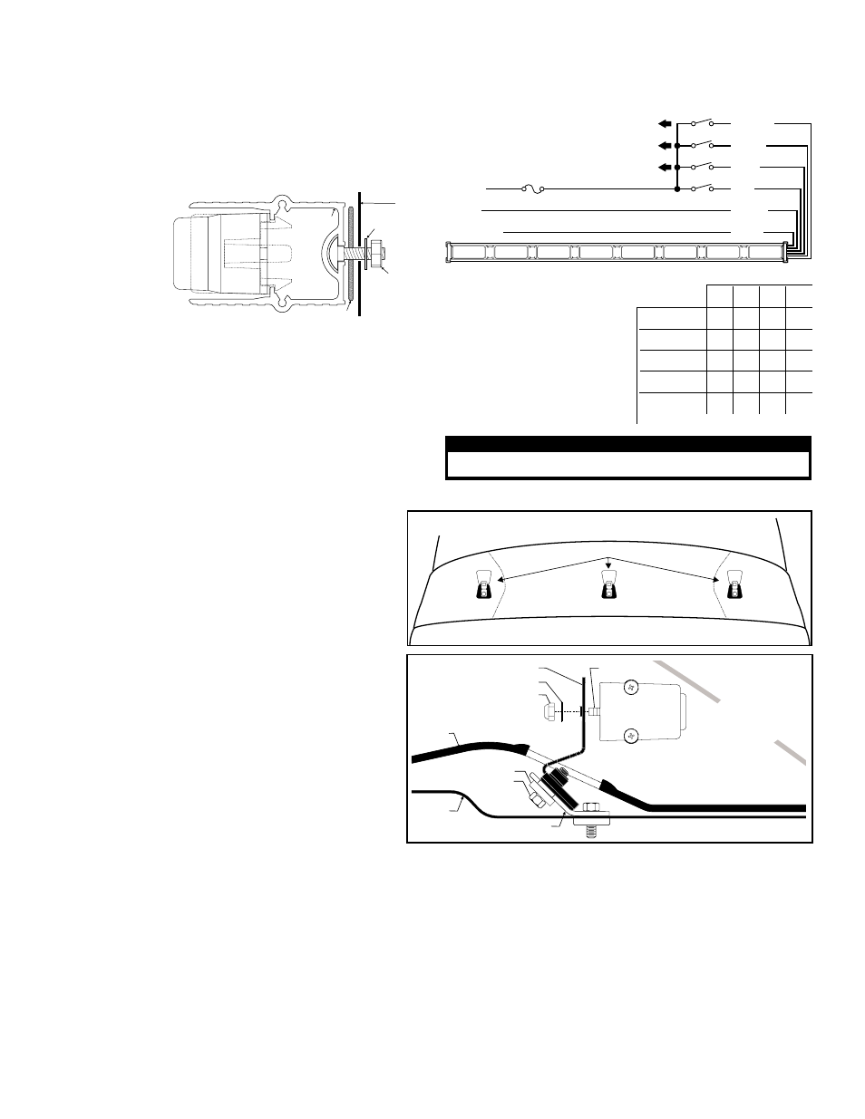
Page 2
Existing bracket for tether strap
holder (Infant car seat)
INSIDE
OF TRUNK
REAR
DECK
5/16 - 18 X 1 Hex Hd Bolt
Spacer
REAR
WINDOW
Mounting Bracket (Qty. 3)
#10 Flat Washer
10 - 24 Elastic
Stop Nut
Fig. 2
10 - 24
Mounting
Bolt
ROOF
REAR WINDOW
CHILD RESTRAINT BRACKETS
Fig. 1
Scan-Lock™
Ground
5 AMP FUSE
+12 VDC
SW2
SW1
T/A Sweep Left
IMPORTANT: Switches must
be sized to accommodate a
minimum of 5 Amps.
WIRING DIAGRAM
SW3
SW4
T/A Sweep Right
Low Power
Scan-Lock™ can select a different pattern
for Traffic Advisor or FLASHERS.
SW1
Left Sweep
Right Sweep
Split Sweep
TA Flasher
Low Power
SW2 SW3 SW4
ON ON OFF OFF
ON OFF ON OFF
ON ON ON OFF
ON OFF OFF OFF
X
X
X ON
S W I T C H E S
FUNCTION
F U N C T I O N
X = Switch position doesn't affect operation.
Traffic Advisor Patterns:
1.
2.
Seq.On (Solid)
Seq.On - Seq.Off
3.
4.
1-Lamp TripleFlash™
2-Lamp TripleFlash™
RED
BLUE
GREEN
ORANGE
BLACK
WHITE
Regular Flash Patterns:
1.
2.
3.
CometFlash®
SingleFlash 375
SingleFlash 150
4. SingleFlash 75
ActionFlash™
ActionScan™
5.
6.
End view of extrusion with endcap removed.
MOUNTING
SURFACE
#10 .631 DIA. X .060
FLAT WASHER
#10-24
ELASTIC
STOP NUT
DISK GASKET
BASE
EXTRUSION
CAUTION! DO NOT LOOK DIRECTLY AT THESE LED’S WHILE THEY ARE ON.
MOMENTARY BLINDNESS AND/OR EYE DAMAGE COULD RESULT!
I M P O R TA N T W A R N I N G !
Installation: Standard Mounting Kit
WARNING! When the Traffic Advisor™ is mounted to the rear of the
vehicle, the cable exit must be on the passenger side. If not, the flash
sequence you choose on the control head will be incorrect. For
example, a left flashing pattern will flash right.
1.
Position the unit in its proposed mounting location to ensure that it fits
properly. Draw a pencil line on the mounting surface using the top and
bottom of the
extrusion as a
guide.
2.
Two 1/4” holes
are required to
mount this unit.
These holes
may be located
anywhere along
the horizontal
centerline of the
unit, but must be
centered between the upper and lower lines made in step 1. It’s best
to locate the mounting holes as far apart as possible.
3.
Drill a hole in each of the areas scribed in the last step (1/4” drill bit).
4.
Slide the 2 carriage bolts (installed in the rear of the bar) over to the 2
mounting holes, install the rubber gaskets onto the bolts as shown
then insert them into the mounting holes
5.
Secure the unit by threading the flat washer and elastic stop nut onto
each bolt and tightening them firmly.
WARNING! All customer supplied wires that connect to the positive ter-
minal of the battery must be sized to supply at least 125% of the maxi-
mum operating current and FUSED at the battery to carry the load. DO
NOT USE CIRCUIT BREAKERS WITH THIS PRODUCT!
Low Power / Orange Wire:
This feature steps the lightbar down to low power for nighttime use. Applying +12 volts to the ORANGE wire holds the
Traffic Advisor in low power mode until voltage is removed. (a toggle switch is recommended).
Scan-Lock™ / White Wire:
Operation: With the lightbar switched on, activate whichever function you wish to change the flash pattern of and follow the instructions below.
TO CYCLE THROUGH ALL PATTERNS: To cycle forward, apply +12 volts to the WHITE wire for less than 1 second and release. To cycle backward, apply
+12 volts to the WHITE wire for more than 1 second and release.
TO SET A PATTERN AS DEFAULT: Allow the pattern to run for more than 5 seconds. The lighthead will now display this pattern when active.
TO RESET TO THE FACTORY DEFAULT PATTERN: Turn off power and apply +12 volts to the WHITE wire while turning power on.
You may want to connect the Scan-Lock™ wire to a switch. An SPST momentary switch is recommended.
IMPORTANT! It is the responsibility of the installation technician
to make sure that the installation and operation of this product will
not interfere with or compromise the operation or efficiency of any
vehicle equipment!
Installation: Child Restraint Bracket
1.
On the rear deck, locate the 3 outboard caps covering the child
restraint strap holders. Remove the plastic covers to access the
tether strap holders (Fig. 1).
2.
Install the mounting bracket as shown in Fig 2. Be sure to tighten
the mounting hardware firmly.
3.
Secure the Traffic Advisor to the mounting bracket as shown using
the provided hardware. Confirm that the Traffic Advisor is level
and clears the 3rd brake light.
4.
Extend the Traffic Advisor wires to your power source. It is left to
the installation technician's discretion to select a path for the wires
that will not damage them or interfere with the operation of any
vehicle components or equipment.
5.
Refer to the Traffic Advisor manual for wiring and fusing.
IMPORTANT! Before returning the vehicle to active service,
visually confirm the proper operation of this product, as well
as all vehicle components/equipment.