Installation, Installation crown vic, Wiring – Whelen TAM63 User Manual
Page 2: Page 2
Page 2
Installation:
Note: When routing wires, it is important to choose a path that will
keep the wires away from excessive heat or any vehicle equipment that
could compromise the wires integrity (trunk lids, door jams, etc.).
WARNING! When the Traffic Advisor™ is mounted to the rear of the
vehicle, the cable exit must be on the passenger side. If not, the flash
pattern sequence you choose on the control head will be incorrect. For
example a left flashing pattern will flash right.
1.
Position the unit in its proposed mounting location to ensure that it fits
properly. Draw a pencil line on the mounting surface using the top and
bottom of the extrusion as a guide.
2.
Two 1/4” holes are required to mount this unit. These holes may be
located anywhere along the horizontal centerline of the unit, but must
be centered between the upper and lower lines made in step 1. Tip! It’s
a good idea to locate the mounting holes as far apart as possible.
3.
Using a 1/4” drill bit, drill a hole in each of the areas scribed in the
previous step.
4.
Remove the endcap without the cable and insert the two carriage bolts
(included) into the extrusion as shown. Position these bolts so they
may pass through the mounting holes drilled in the previous step.
5.
With the unit in position, place a gasket, flat washer and elastic stop nut onto
each bolt and tighten firmly.
Installation Crown Vic:
1.
Locate and remove the plastic covers over the tether strap holders on the
rear deck, exposing the necessary brackets.
2.
Place the lightbar onto the rear deck. The lightbar carriage bolts should
already be installed as outlined in the first installation. Center the
lightbar directly behind the third
brake light.
3.
Position the TAM83CV bracket
as shown and mount it to the
vehicle bracket using the
hardware provided. Do not
tighten this hardware yet.
4.
Lift the lightbar into position with
the lightbar mounting bolts
inserted through the bracket.
Secure the lightbar to the
mounting bracket. Do not tighten
this hardware yet.
5.
Straighten the mounting brackets
and tighten the appropriate
hardware. Now tighten the hardware securing the lightbar to the mounting
bracket.
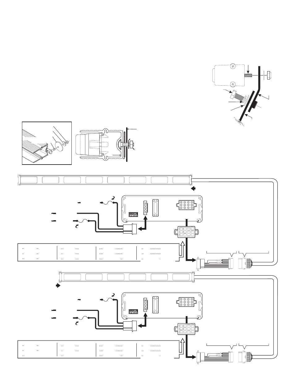
Wiring:
Extend the control wires to your switch panel and make the appropriate
connections using the wiring information below. TACTRLD1 is shown. If your
system uses another control head, refer to your control head manual for
connection and operation.
POS 2 / BLACK
POS 2 / BLACK
3 Amp
Fuse
3 Amp
Fuse
10 Amp
Fuse
10 Amp
Fuse
POS 1 / RED
POS 1 / RED
POS 3 / WHITE
POS 3 / WHITE
BATTERY: Negative
BATTERY: Negative
BACK LIGHT CONTROL: to +12VDC
source that is activated with the vehicles ignition switch
BACK LIGHT CONTROL: to +12VDC
source that is activated with the vehicles ignition switch
BATTERY: Positive
BATTERY: Positive
TACTLD1
REAR VIEW
TACTLD1
REAR VIEW
1
1
2
2
4
4
5
5
6
6
3
3
7
7
10
10
8
8
11
11
9
9
12
12
1
1
1
1
1
1
1
1
1
1
2
3
4
5
6
7
8
9
IO
11
12
13
14
15
16
= BROWN
= RED
= ORANGE
= YELLOW
= GREEN
= BLUE
= VIOLET
= GRAY
= WHITE-BROWN
= WHITE-RED
= WHITE-ORANGE
= WHITE-YELLOW
= WHITE-GREEN
= WHITE-BLUE
= WHITE-VIOLET
= WHITE-GREY
1
1
1
1
1
1
1
1
1
1
2
3
4
5
6
7
8
9
IO
11
12
13
14
15
16
= BROWN
= RED
= N/C
= YELLOW
= GREEN
= N/C
= VIOLET
= GRAY
= WHITE-BROWN
= WHITE-RED
= N/C
= WHITE-YELLOW
= WHITE-GREEN
= N/C
= WHITE-VIOLET
= WHITE-GREY
DIP
SWITCH
CONTROL
DIP
SWITCH
CONTROL
12 POSITION
CONNECTOR
12 POSITION
CONNECTOR
20
AMP
20
AMP
NOTE: For all information on programming and function refer to the control head instructions.
NOTE: For all information on programming and function refer to the control head instructions.
NOTE: Switches fuses and fuse blocks are not supplied
TAM83 / TAM83CV & TAM8348
TAM63
NOTE: Switches fuses and fuse blocks are not supplied
1
1
2
2
3
3
4
4
5
5
6
6
7
8
1
1
1
1
1
1
1
1
1
1 = WHITE
2
3
4
5
6
7
8
9
IO
11
12
13
14
15
16
= WHITE
= WHITE
= WHITE
= WHITE
= WHITE
= WHITE
= WHITE
= WHITE-BROWN
= WHITE-RED
= WHITE-ORANGE
= WHITE-YELLOW
= WHITE-GREEN
= WHITE-BLUE
= WHITE-VIOLET
= WHITE-GREY
1
1
1
1
1
1
1
1
1
1 = WHITE
2
3
4
5
6
7
8
9
IO
11
12
13
14
15
16
= WHITE
= WHITE
= WHITE
= WHITE
= WHITE
= WHITE
= WHITE
= WHITE-BROWN
= WHITE-RED
= WHITE-ORANGE
= WHITE-YELLOW
= WHITE-GREEN
= WHITE-BLUE
= WHITE-VIOLET
= WHITE-GREY
4
5
6
4
5
6
1
2
3
1
2
3
7
8
9
7
8
9
10
11
12
10
11
12
Lamp 4
Lamp 5
Lamp 6
Lamp 3
Lamp 4
N/C
Lamp 1
Lamp 2
Lamp 3
Lamp 1
Lamp 2
N/C
Lamp 7
Lamp 8
Batt. / Pos
Lamp 5
Lamp 6
Batt. / Pos
N/C
N/C
Aux. Input
N/C
N/C
Aux. Input
YELLOW
GREEN
BLUE
YELLOW
GREEN
BROWN
RED
ORANGE
BROWN
RED
VIOLET
GRAY
WHITE
VIOLET
GRAY
WHITE
N/C
N/C
WHT-BLU
N/C
N/C
WHT-BLU
L I G H T H E A D
CONNECTIONS
LIGHTHEAD CONNECTIONS
BROWN (+)
WHITE-BROWN (-)
BROWN (+)
WHITE-BROWN (-)
RED (+)
WHITE-RED (-)
RED (+)
WHITE-RED (-)
ORANGE (+)
WHITE-ORANGE (-)
YELLOW (+)
WHITE-YELLOW (-)
YELLOW (+)
WHITE-YELLOW (-)
GREEN (+)
WHITE-GREEN (-)
GREEN (+)
WHITE-GREEN (-)
BLUE (+)
WHITE-BLUE (-)
VIOLET (+)
WHITE-VIOLET (-)
VIOLET (+)
WHITE-VIOLET (-)
GREY (+)
WHITE-GREY (-)
GREY (+)
WHITE-GREY (-)
Use SP/ST switch
fused at 3 Amps.
Use SP/ST switch
fused at 3 Amps.
TAM83
Lightbar
Mounting Bolt
Lightbar
Mounting
Hardware
Tether Strap
Bracket
5/16”
Hex Bolt
5/16”
Lockwasher
3/8”
Flat Washer
TAM83CV
Mounting
Bracket
#10-24 Elastic Stop Nut
#10 Flat washer
.631" Dia. x .060
Disc Gasket
#10-24 x 5/8" LG SS
Carriage Bolt
End view of extrusion / Endcap removed
FLAT
WASHER
DISK GASKET
EXTRUSION