Installation, Wiring, Page 2 – Whelen TAZ66 User Manual
Page 2: Important warning
Page 2
3 Amp
Fuse
3 Amp
Fuse
15 Amp
Fuse
15 Amp
Fuse
BATTERY: Negative
BATTERY: Negative
BACKLIGHT CONTROL
To +12VDC source that is activated with vehicle ignition switch
To +12VDC source that is activated with vehicle ignition switch
BACKLIGHT CONTROL
BATTERY: Positive
BATTERY: Positive
TACTLD1
REAR VIEW
TACTLD1
REAR VIEW
1
1
2
2
4
4
5
5
6
6
3
3
7
7
10
10
8
8
11
11
9
9
12
12
1
1
1
1
1
1
1
1
1
1
2
3
4
5
6
7
8
9
IO
11
12
13
14
15
16
= BROWN
= RED
= N/C
= YELLOW
= GREEN
= N/C
= VIOLET
= GRAY
= WHITE-BROWN
= WHITE-RED
= N/C
= WHITE-YELLOW
= WHITE-GREEN
= N/C
= WHITE-VIOLET
= WHITE-GREY
1
1
1
1
1
1
1
1
1
1
2
3
4
5
6
7
8
9
IO
11
12
13
14
15
16
= BRN
= RED
= N/C
= YEL
= GRN
= N/C
= VIO
= GRY
= WHT-BRN
= WHT-RED
= N/C
= WHT-YEL
= WHT-GRN
= N/C
= WHT-VIO
= WHT-GRY
1
1
1
1
1
1
1
1
1
1
2
3
4
5
6
7
8
9
IO
11
12
13
14
15
16
= BRN
= RED
= ORG
= YEL
= GRN
= BLU
= VIO
= GRY
= WHT-BRN
= WHT-RED
= WHT-ORG
= WHT-YEL
= WHT-GRN
= WHT-BLU
= WHT-VIO
= WHT-GRY
DIP
SWITCH
CONTROL
DIP
SWITCH
CONTROL
12 POSITION
CONNECTOR
12 POSITION
CONNECTOR
20
AMP
20
AMP
NOTE:
For programming and function refer to control head
instructions. Switches fuses & fuse blocks not supplied
NOTE:
For programming and function refer to control head
instructions. Switches, fuses & fuse blocks not supplied
TAZ86AA / TAZ86RB
TAZ66 / TAZ86
FLASHER
1
2
3
4
5
6
FLASHER
1
2
3
4
5
6
7
8
1
1
1
1
1
1
1
1
1
1 = WHITE
2
3
4
5
6
7
8
9
IO
11
12
13
14
15
16
= WHITE
= WHITE
= WHITE
= WHITE
= WHITE
= WHITE
= WHITE
= WHITE-BROWN
= WHITE-RED
= WHITE-ORANGE
= WHITE-YELLOW
= WHITE-GREEN
= WHITE-BLUE
= WHITE-VIOLET
= WHITE-GREY
1
1
1
1
1
1
1
1
1
1 = WHT
2
3
4
5
6
7
8
9
IO
11
12
13
14
15
16
= WHT
= WHT
= WHT
= WHT
= WHT
= WHT
= WHT
= WHT-BRN
= WHT-RED
= WHT-ORG
= WHT-YEL
= WHT-GRN
= WHT-BLU
= WHT-VIO
= WHT-GRY
4
5
6
4
5
6
1
2
3
1
2
3
7
8
9
7
8
9
10
11
12
10
11
12
Lamp 4
Lamp 5
Lamp 6
Lamp 4
Lamp 5
Lamp 6
Lamp 1
Lamp 2
Lamp 3
Lamp 1
Lamp 2
Lamp 3
Lamp 7
Lamp 8
Batt. / Pos
Lamp 7
Lamp 8
Batt. / Pos
N/C
N/C
Aux. Input
N/C
N/C
Aux. Input
YELLOW
GREEN
BLUE
YELLOW
GREEN
BLUE
BROWN
RED
ORANGE
BROWN
RED
ORANGE
VIOLET
GRAY
WHITE
VIOLET
GRAY
WHITE
N/C
N/C
WHT-BLU
N/C
N/C
WHT-BLU
C o n n e c t o r s g o i n g t o L i g h t h e a d s
C o n n e c t o r s g o i n g t o L i g h t h e a d s
8 LIGHT
Use SP/ST switch
fused at 3 Amps.
Use SP/ST switch
fused at 3 Amps.
POS
3/WHITE
POS
3/WHITE
POS
2/BLK
POS
2/BLK
POS
1/RED
POS
1/RED
WHT/ORG Flasher Gnd
ORG Flasher Pos. (+)
WHT/BLU Flasher Gnd
BLUE Flasher Pos. (+)
B R O W N
WHT/BRN
ORANGE
WHT/ORG
POS. +
NEG. -
( )
( )
B R O W N
WHT/BRN
RED
WHT/RED
RED
WHT/RED
ORANGE
WHT/ORG
YELLOW
WHT/YEL
G R E E N
WHT/GRN
BLUE
WHT/BLU
VIOLET
WHT/VIO
GREY
WHT/GRY
G R E E N
WHT/GRN
YELLOW
WHT/YEL
VIOLET
WHT/VIO
GREY
WHT/GRY
BLUE
WHT/BLU
6 LIGHT
6 or 8 LIGHT
POS. +
NEG. -
( )
( )
B R O W N
WHT/BRN
RED
WHT/RED
G R E E N
WHT/GRN
YELLOW
WHT/YEL
VIOLET
WHT/VIO
GREY
WHT/GRY
POS. +
NEG. -
( )
( )
8 Li ht
g
6 Li ht
g
CAUTION! DO NOT LOOK DIRECTLY AT THESE LEDS WHILE THEY ARE ON.
MOMENTARY BLINDNESS AND/OR EYE DAMAGE COULD RESULT!
IMPORTANT WARNING!
Installation:
IMPORTANT: It is the responsibility of the installation technician to make sure
that the installation and operation of this product will not interfere with or
compromise the operation or efficiency of any vehicle equipment!
Note: When routing wires, it is important to choose a path that will keep the
wires away from excessive heat or any vehicle equipment that could
compromise the wires integrity (trunk lids, door jams, etc.).
WARNING! When the Traffic Advisor is mounted to the rear of the vehicle, the
cable exit must be on the passenger side. If not, the flash pattern sequence you
choose on the control head will be incorrect. For example, a left flashing
pattern will flash right.
Caution: Permanent mounting of this product will require drilling. It is
absolutely necessary to make sure that no other vehicle components could be
damaged by this process. Check both sides of the mounting surface before
starting. If damage is likely, select a different location.
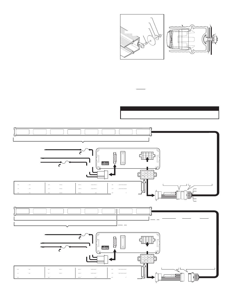
1.
Position unit in its proposed mounting location. Draw a pencil line on the
mounting surface using the top and bottom of the extrusion as a guide.
2.
Two 1/4” holes are required for mounting. The holes may be located anywhere
along the horizontal centerline of the unit, but must be centered between the
upper and lower lines made in step 1. Locate the mounting holes as far apart
as possible.
3.
Using a 1/4” drill bit, drill a hole in each of the areas scribed in the previous
step.
4.
Remove the end cap without the cable and insert the two carriage bolts
(included) into the extrusion as shown. Position these bolts so they may pass
through the mounting holes drilled in the previous step.
5.
With the unit in position, place a gasket, flat washer and elastic stop nut onto
each bolt and tighten firmly.
Wiring:
Extend the control wires to your switch panel and make the connections using the
wiring information below. TACTRLD1 is shown. If your system uses another control
head, refer to your control head manual for connection and operation.
WARNING!
All customer supplied wires that connect to the positive terminal
of the battery must be sized to supply at least 125% of the maximum operating
current and FUSED at the battery to carry that load. DO NOT USE CIRCUIT
BREAKERS WITH THIS PRODUCT!
IMPORTANT! Before returning the vehicle to active service, visually confirm
the proper operation of this product, as well as all vehicle components/
equipment.
#10-24 Elastic Stop Nut
#10 Flat washer
.631" Diameter
Disc Gasket
#10-24 X 5/8" LG SS
Carriage Bolt
End view of extrusion with endcap removed.
#10
.631"
DIA.
#10-24
ELASTIC ST
OP
NUT
DISK GASKET
BASE
EXTRUSION
MOUNTING
SURFACE