Service, Installation, Wiring – Whelen TANF65 User Manual
Page 2: Operation, Control cable identification, Important warning, Page 2
Page 2
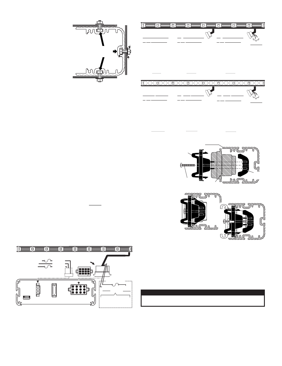
BRACKET
4 X 1-3/8
PHILLIPS PAN
HEAD PLASTILOC SCREW
Loosen screw, squeeze
bracket and pull out.
Side view of
with Lighthead and Bracket
Extrusion
LIGHTHEAD
squeeze together
pull out
CLAMP
NUT
TACF85
Ne ative Switchin
g
g
TOR
Ground Lamp 1
Ground Lamp 2
Ground Lamp 3
Ground Lamp 4
Ground Lamp 5
Ground Lamp 6
Ground Lamp 7
Ground Lamp 8
+12VDC
/
/
/
/
/
/
/
/
12 PIN CONNECTOR
1 BRN
2 RED
3 ORG
4 YEL
5 GRN
6 BLU
7 VIO
8 GRY
9 WHT
Positions 10 thru 12 - N/C
-
-
-
-
-
-
-
-
-
SCCF85
Positive Switching
TOR
+12VDC / Lamp 1
+12VDC / Lamp 2
+12VDC / Lamp 3
+12VDC / Lamp 4
+12VDC / Lamp 5
+12VDC / Lamp 6
+12VDC / Lamp 7
+12VDC / Lamp 8
Ground
12 PIN CONNECTOR
1 BRN
2 RED
3 ORG
4 YEL
5 GRN
6 BLU
7 VIO
8 GRY
9 WHT
Positions 10 thru 12 - N/C
-
-
-
-
-
-
-
-
-
TACF85**
Ne ative switchin
g
g
TOR
Ground Lamp 1
Ground Lamp 2
Ground Lamp 3
Ground Lamp 4
Ground Lamp 5
Ground Lamp 6
+12VDC
/
/
/
/
/
/
12 PIN CONNECTOR
1 BRN
2 RED
3 NC
4 YEL
5 GRN
6 NC
7 VIO
8 GRY
9 WHT
Positions 10 thru 12 - N/C
-
-
-
-
-
-
-
-
-
TANF85/TAMF85
Ne ative Switchin
g
g
TOR
Ground / Lamp 1
Ground / Lamp 2
Ground / Lamp 3
Ground / Lamp 4
Ground / Lamp 5
Ground / Lamp 6
Ground / Lamp 7
Ground / Lamp 8
+12 VDC
12 PIN CONNECTOR
1 BRN
2 RED
3 ORG
4 YEL
5 GRN
6 BLU
7 VIO
8 GRY
9 WHT
-
-
-
-
-
-
-
-
-
Positions 10 thru 12 - N/C
SCNF85/SCMF85
Positive Switching
TOR
+12VDC / Lamp 1
+12VDC / Lamp 2
+12VDC / Lamp 3
+12VDC / Lamp 4
+12VDC / Lamp 5
+12VDC / Lamp 6
+12VDC / Lamp 7
+12VDC / Lamp 8
GROUND
12 PIN CONNECTOR
1 BRN
2 RED
3 ORG
4 YEL
5 GRN
6 BLU
7 VIO
8 GRY
9 WHT
-
-
-
-
-
-
-
-
-
Positions 10 thru 12 - N/C
TANF85**
Ne ative Switchin
g
g
TOR
Lamp 3
Lamp 6
Ground Lamp 1
Lamp 2
Ground
Ground Lamp 3
Ground Lamp 4
Ground Lamp 5
Ground Lamp 6
/
/
/
/
/
/
+12 VDC
12 PIN CONNECTOR
1 BRN
2 RED
3 NC
4 YEL
5 GRN
6 NC
7 VIO
8 GRY
9 WHT
Positions 10 thru 12 - N/C
-
-
-
-
-
-
-
-
-
ORG
BLU
- +12VDC
Ground
-
FLASHER
ORG
BLU
- +12VDC
Ground
-
FLASHER
Control Cable Identification
Service:
This section shows
you how to access
the lightbar for
service or lighthead
replacement.
Loosen the set
screw(s) on the
bracket, squeeze
the brackets clip
together so that it
disengages from
the extrusion and
pull the bracket
straight out. With
the bracket
removed the
lighthead lifts out
and can be
unplugged from the harness and removed
from the lightbar.
IMPORTANT! It is the responsibility of the installation technician to
make sure that the installation and operation of this product will not
interfere with or compromise the operation or efficiency of any vehicle
equipment!
IMPORTANT! Before returning this vehicle to active service, visually
confirm the proper operation of this product, as well as all vehicle
components/equipment.
Installation:
Note: When routing wires, it
is very important that you
choose a path that will keep
the wires away from any
excessive heat or any vehicle
equipment that could
compromise the integrity of
the wires (ex. trunk lids, door
jams, etc.).
Note: Permanent mounting
of this product will require
drilling. It is absolutely
necessary to make sure that
no other vehicle components could be damaged by this process.
Check both sides of the mounting surface before starting. If
damage is likely, select a different mounting location.
1.
Position the unit onto its mounting location. Draw a pencil line onto
the mounting surface along the top and bottom of the extrusion
and a “centerline” centered between the two.
2.
Four 13/64” holes are required to mount this unit. These holes may
be located anywhere along the horizontal centerline that you drew
in step one. It’s best to locate the holes as far apart as possible.
Mark the hole locations onto the mounting surface.
3.
Using a #9 drill bit, drill a hole in each of the hole locations marked.
4.
Remove the endcap and slide the hex-head mounting bolts
(included) into any one of the three channels provided on the
extrusion (use the top, rear or bottom channel depending on which
position you wish to mount the unit) and reinstall the endcap.
5.
Align these bolts with the 4 mounting holes and insert them into
the mounting holes.
6.
Install a flat washer and elastic stop nut onto each bolt and tighten.
Wiring:
WARNING: All customer supplied wires that connect to the posi-
tive terminal of the battery must be sized to supply at least 125%
of the maximum operating current and FUSED at the battery to
carry that load. DO NOT USE CIRCUIT BREAKERS WITH THIS
PRODUCT!
Operation:
Connect the Traffic Advisor™ to your control head as shown in the
wiring diagram below and follow the instructions included with the
control head for operation.
FUSE
Dip
Switches
Rear View / TACTLD1
control head
shown. Connection is the same for
.
Negative switching
Positive Switching
1
5
2 3 4
ORG:
+12V
Flashers
BLU:
Ground
Flashers
Secure
wire to ground.
Apply +12 volts to
wire to engage flashers.
SignalAlert™ 75 PHASE 2
BLUE
ORANGE
A
Fuse @
5 MPS
Backlight control
(To accessory switch)
To positive (+) battery
To chassis ground
3 A
Fuse @
MPS
10 AMP
Fuse @
RED / Pos.1
WHT / Pos.3
BLK / Pos.2
12 POSITION
CONNECTOR
REAR VIEW
12
2
3
5
6
9
8
11
10
1
4
7
Flasher Models
W i r i n g
Diagram
CAUTION! DO NOT LOOK DIRECTLY AT THESE LEDS WHILE THEY ARE ON.
MOMENTARY BLINDNESS AND/OR EYE DAMAGE COULD RESULT!
IMPORTANT WARNING!
#10-24 ELASTIC
ST
OP
NUT
#10 FLA
T
W
A
SHER
Extrusion end view (without end cap)
MOUNTING SURFACE
MOUNTING SURFACE
#10-24 X 3/4"
HEX HEAD
Mount to any 1
o f 3 c h a n n e l s
in the extrusion