Installation, Wiring, Operation – Whelen TADF6 User Manual
Page 2: Service
Page 2
#8 LED
#7 LED
#6 LED
#5 LED
#4 LED
#3 LED
#2 LED
#1 LED
MOMENTARY
switch
Battery
BLACK
GROUND
BLUE
RED
BLACK
GREY
LEFT TA
POSITIVE
WARNING
RIGHT TA
WHITE
SCANLOCK
10 AMP
F U S E
1 AMP
FUSES
SPST switches
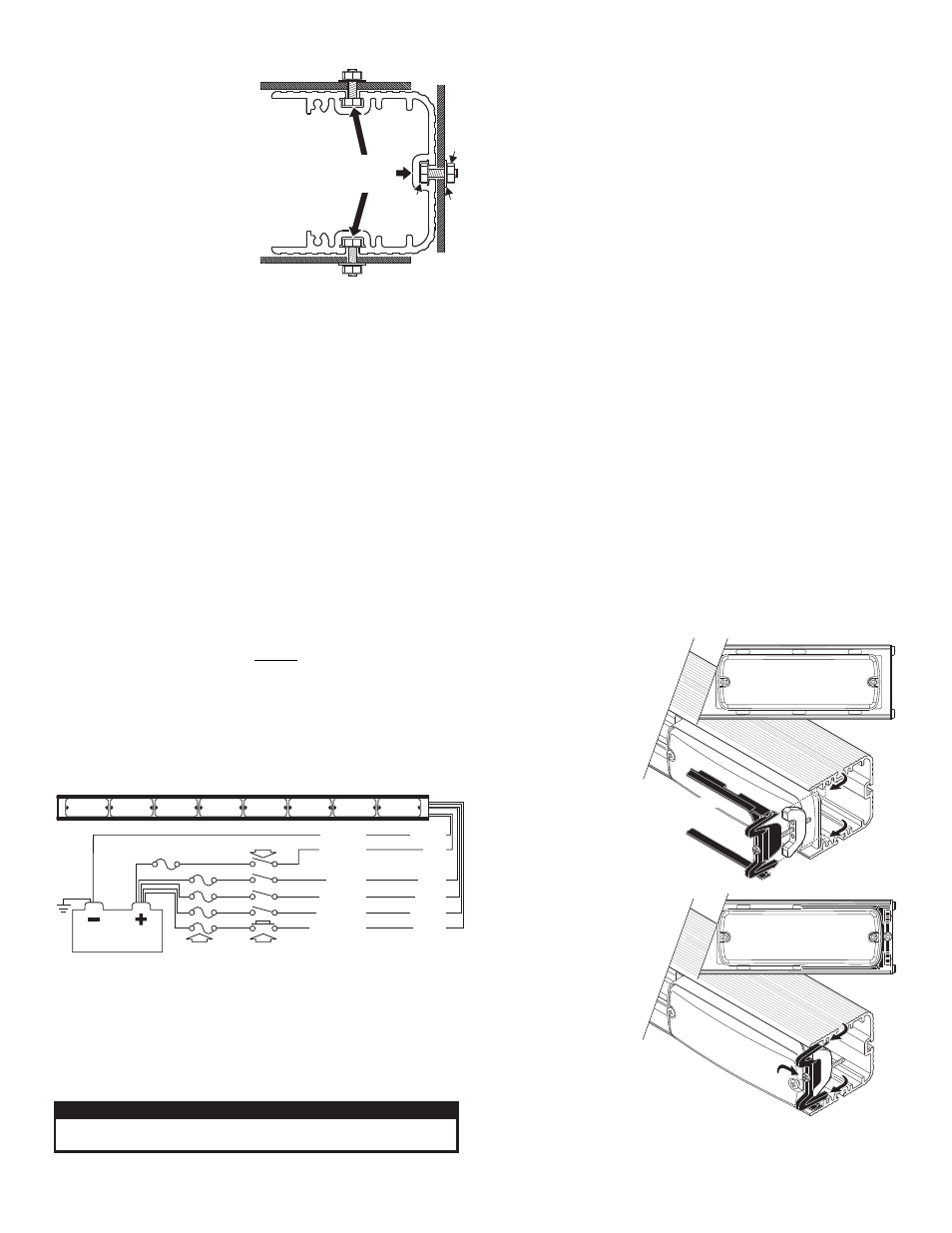
Snap
bracket into
extrusion, over
lighthead. Bracket
fits around lighthead (End
bracket shown. all brackets
will mount in the same manner).
Tighten the screw on the bracket to secure it.
FRONT VIEW
FRONT VIEW
Place lighthead
into extrusion
Snap-In
Snap-In
Tighten
Screw
Snap-In
Snap-In
#10-24
ELASTIC
ST
OP
NUT
#10
FLA
T
W
A
SHER
Extrusion end view (without end cap)
MOUNTING SURFACE
MOUNTING SURFACE
#10-24 X 3/4"
HEX HEAD
Mount to any 1
o f 3 c h a n n e l s
in the extrusion
Installation:
Note: When routing wires, it is
very important that you choose
a path that will keep the wires
away from any excessive heat or
any vehicle equipment that
could compromise the integrity
of the wires (ex. trunk lids, door
jams, etc.).
Note: Permanent mounting of
this product will require drilling.
It is absolutely necessary to
make sure that no other vehicle
components could be damaged
by this process. Check both sides of the mounting surface before
starting. If damage is likely, select a different mounting location.
1.
Position the unit onto its mounting location. Draw a pencil line onto
the mounting surface along the top and bottom of the extrusion and a
“centerline” centered between the two.
2.
Four
3/16” holes are required to mount this unit. These holes may be
located anywhere along the horizontal centerline that you drew in
step one. It’s best to locate the holes as far apart as possible. Mark
the hole location onto the mounting surface.
3.
Drill a hole in each of the hole locations marked.
4.
Insert the four hex-head mounting bolts (included) into the bolt head
access provided in the channel at either the top, bottom or rear of the
extrusion.
5.
Slide the bolts along the track and align them with the 4 mounting
holes, than insert them into the mounting holes.
6.
Install a flat washer and elastic stop nut onto each bolt and tighten.
Wiring:
WARNING: All customer supplied wires that connect to the positive
terminal of the battery must be sized to supply at least 125% of the
maximum operating current and FUSED at the battery to carry that
load. DO NOT USE CIRCUIT BREAKERS WITH THIS PRODUCT!
Wire Connections:
Extend the RED wire to the battery and install a 10 amp fuse block
(customer supplied) on the end of the wire. Remove the fuse before
connecting any wires to the battery. Connect the RED wire to the
POSITIVE (+) battery terminal.
IMPORTANT: Leave no more than 2 feet of wire between fuse block
and battery. The wire between fuse and battery is unprotected, do
not allow this wire to come in contact with any other wires.
Extend the BLACK wire to the battery and connect it to the battery ground.
If your vehicle has a cable extending from the negative terminal of the
battery to the chassis, it is best to attach the black wire at the chassis
connection.
Operation:
Scan-Lock™ (WHITE)
In order to program flash patterns, the lightbar must be on and either
LEFT or RIGHT TA or WARNING must be powered up.
TO CHANGE PATTERNS: To cycle forward to the next available pattern
apply +12 volts to the WHITE wire for less than 1 second and release.
To cycle back to the previous pattern apply +12 volts to the WHITE wire
for more than 1 second and release.
TO CHANGE THE DEFAULT PATTERN: When the desired pattern is
displayed, allow it to run for more than 5 seconds. The light will now
display this pattern when initially activated.
TO RESTORE THE FACTORY DEFAULT PATTERN: This will reset all
patterns back to there default settings. Disconnect main power and apply
power to the WHITE wire. With power applied to the WHITE wire, turn
main power back on. After 3 seconds remove power from the WHITE wire.
A Normally Open momentary switch should be used to control Scan-
Lock™ operation.
The following is a list of all the available flash patterns:
Service:
This section shows you
how to access the lightbar
for service or lighthead
replacement. To replace a
lighthead, first loosen the
set screw(s) on the
bracket. Now squeeze the
clip together so that it
disengages from the
extrusion and pull the
bracket straight out. With
the bracket removed the
lighthead lifts out and can
be unplugged from the
harness and removed
from the lightbar.
IMPORTANT! It is the
responsibility of the
installation technician
to make sure that the
installation and
operation of this
product will not
interfere with or
compromise the
operation or efficiency
of any vehicle
equipment! Before
returning the vehicle to
active service, visually
confirm the proper
operation of this product, as well as all vehicle components/
equipment.
RED . . . . . . . . . Positive / Apply +VBAT to Power Lightbar . . . . . FUSE @ 10 AMPS
BLACK. . . . . . . Negative / Connect to Ground. . . . . . . . . . . . . . . . . . . . . . . . . . . N/A
BLUE . . . . . . . . Apply +VBAT and the TA Sweeps LEFT . . . . . . . . FUSE @ 1 AMP
GREY . . . . . . . . Apply +VBAT and the TA Sweeps RIGHT . . . . . . . FUSE @ 1 AMP
BLACK. . . . . . . Apply +VBAT and ALL Lights FLASH . . . . . . . . . . . FUSE @ 1 AMP
WHITE . . . . . . . Scan-Lock™ Flash Pattern Selection . . . . . . . . . . . FUSE @ 1 AMP
BLU & GRY . . . Apply +VBAT to both the BLUE and GREY wires for SPLIT TA
CAUTION! DO NOT LOOK DIRECTLY AT THESE LEDS WHILE THEY ARE ON.
MOMENTARY BLINDNESS AND/OR EYE DAMAGE COULD RESULT!
IMPORTANT WARNING!
Flash Patterns:
1. SignalAlert™75
2. CometFlash® 75
3. SingleFlash 300
4. SingleFlash 120
5. SingleFlash 75
6. ActionFlash™
7. ActionScan™
TA Direction
1. Sequence On Solid
2. 1 Lamp TripleFlash™
3. 2 Lamp TripleFlash™