Mounting, Ref. a, Page 2 ref. a. optional mounting – Whelen TAM65 User Manual
Page 2
Page 2
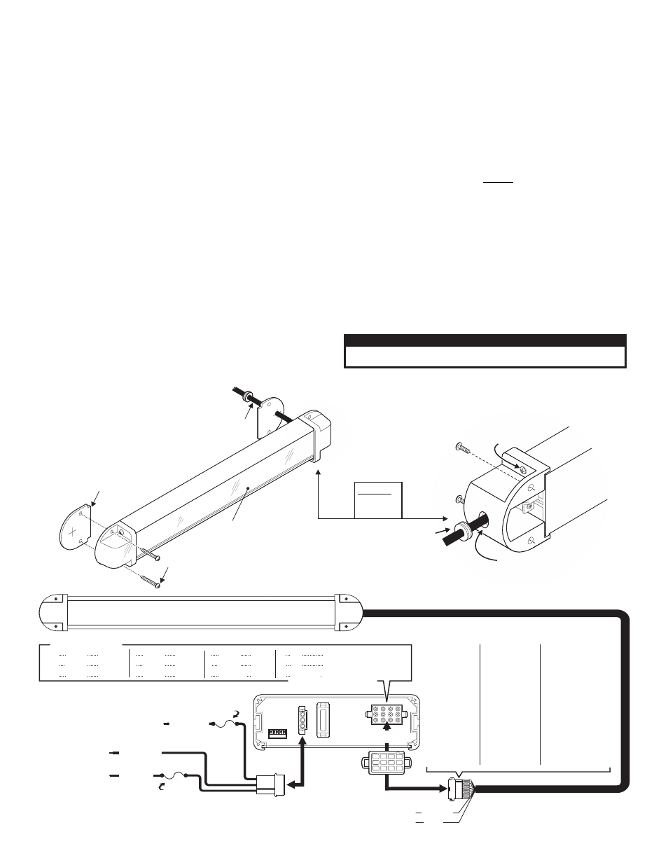
REF. A.
Optional
Mounting
5/8 Grommet
Shown here on wire harness
for illustration purposes.
"
goes in wire hole.
Lens
#10 X 3/4" P.P.H.S.M.S.
Endcap
Seal
REF. A
OPTIONAL MOUNTING
Cable
Harness
#10 - 24 X 1.25
TX P. HD.
Drill hole in endcap,
run cable through.
CAUTION! DO NOT LOOK DIRECTLY AT THESE LED’S WHILE THEY ARE ON.
MOMENTARY BLINDNESS AND/OR EYE DAMAGE COULD RESULT!
I M P O R TA N T W A R N I N G !
Mounting:
Note: Permanent mounting of this product will require drilling. It is
absolutely necessary to make sure that no other vehicle components
could be damaged by this process. Check both sides of the
mounting surface before starting. If damage is likely, select a
different mounting location.
Note: When routing the wires, it is important to choose a path that
will keep these wires away from excessive heat and from any vehicle
equipment that could compromise the integrity of the wires (ex.
trunk lids, door jams, etc.).
There are two ways to mount the light array. Both require the unit to be
secured to the mounting surface using sheet metal screws (supplied). The
cable harness can either be routed directly into the mounting surface or
out the side of the end cap (see below). When facing the LED. display, the
cable harness should exit from the right side of the bar.
Note: When the Traffic Advisor is mounted to the rear of the vehicle,
the cable exit must be on the passenger side. If not, the flash pattern
sequence you choose on the control head will be incorrect. For
example, a left flashing pattern will flash right.
1.
Position the unit in its proposed mounting location to ensure that it fits
properly. With the unit in place, use an awl or other suitable tool and
scribe the areas to be drilled, based on the desired style.
Style 1 - Remove the unit from its mounting area and, using a 5/8” drill bit,
drill a hole for the cable harness. Affix the 5/8” grommet to the hole and
feed the cable harness through the grommet.
Style 2 (OPTIONAL) - To route the cable harness through the end cap a 5/
8” passage hole must be drilled. Remove the endcap from the light array
via the machine screws, so as to prevent damage
to the cable harness, and drill the hole. Place the 5/8” grommet on the
hole and feed the cable through. Once this is done, secure the endcap
back onto the light array.
2.
Using an appropriately sized drill bit, drill a hole in each of the areas
scribed in the previous step.
3.
Return the unit to its mounting location and, using the supplied
hardware, mount the unit as shown below.
WARNING! All customer supplied wires that connect to the positive
terminal of the battery must be sized to supply at least 125% of the
maximum operating current and FUSED at the battery to carry that
load. DO NOT USE CIRCUIT BREAKERS WITH THIS PRODUCT!
Note: Do not install the fuse required in the fuse block, until all wire
connections are completed.
Installation is now complete. Refer to the wiring diagram below and the
manual that comes with your control head.
IMPORTANT: It is the responsibility of the installation technician to
make sure that the installation and operation of this product will not
interfere with or compromise the operation or efficiency of any
vehicle equipment! Before returning the vehicle to active service,
visually confirm the proper operation of this product, as well as all
POS 1 / RED
POS 2 / BLACK
POS 3 / WHITE
BATTERY: Negative
BACK LIGHT CONTROL: to +12VDC
source that is activated with the vehicles ignition switch
BATTERY: Positive
10 Amp
Fuse
3 Amp
Fuse
4 5
3
2
1
TACTLD1 / REAR VIEW
1
2
4
5
6
3
7
10
8
11
9
12
TAM65 / TAM85 / TAM85_ _ / TAM65W / TAM85W / TAM85W_ _
DIP
SWITCH
CONTROL
12 POSITION
CONNECTOR
20
AMP
PIN
4
5
6
1
2
3
7
8
9
10
11
12
FUNCTION
Lamp 4
Lamp 5
Lamp 6
Lamp 1
Lamp 2
Lamp 3
Lamp 7
Lamp 8
Batt. / Pos
N/C
N/C
Aux. Input
SP/ST switch fused at 3 Amps.
Requires an
COLOR
YELLOW
GREEN
BLUE
BROWN
RED
ORANGE
VIOLET
GRAY
WHITE
N/C
N/C
WHITE-BLUE
NOTE: For
programming and function information,
refer to the instructions that are supplied with the control head.
TACTLD1
NOTE: Switches fuses and fuse blocks are not supplied
1 = BROWN
2 =
3 =
4 =
5 =
6 =
7 =
8 =
9 =
IO =
11 =
12 =
RED
N/C
YELLOW
GREEN
N/C
VIOLET
GRAY
WHITE
N/C
N/C
N/C
TAM65 & TAM65W
6 LT / SW. GND.
1 = BROWN
2 =
3 =
4 =
5 =
6 =
7 =
8 =
9 =
1O
11
12
RED
ORANGE
YELLOW
GREEN
BLUE
VIOLET
GRAY
WHITE
= N/C
= N/C
= N/C
TAM85 & TAM85W
8 LT / SW. GND.
1 = BROWN
2 =
3 =
4 =
5 =
6 =
7 =
8 =
9 =
IO =
11 =
12 =
RED
N/C
YELLOW
GREEN
N/C
VIOLET
GRAY
WHITE
N/C
N/C
N/C
TAM85_ _ & TAM85W_ _
8 LT / SW. GND.
Flasher wires are only present on: TAM85_ _
FLASHER POWER (to +12V / fuse @ 5A)
ORANGE
FLASHER GROUND
BLUE