Replacing or servicing a lighthead, Replacing a halogen snap-in bulb, Installation: mounting the traffic advisor – Whelen TA637A User Manual
Page 2: Fig. 1 mounting foot kit
Page 2
NOTE: Replacing a lens or halogen bulb does not require removing
the lighthead.
4 LIGHT T.A.:
-
Disconnect lightbar from power
and remove the endcap on the side that you wish
to replace the lighthead. Slide the lighthead you wish
to replace out of the base. Cut the wires off of the old lighthead (removing
the butt splice) then, using a new butt splice, install the new lighthead then
slide the lighthead(s) back into the base.
Replacing or Servicing a Lighthead:
6 or 8 LIGHT T.A.:
-
-
Disconnect lightbar from power and remove the
end cap on the side of the bar that the cable exits on. Slide the lightheads
out of the bar until you reach the one you are replacing. Cut the wires off
of the old lighthead (removing the old butt splice) then, butt splice
the new lighthead and slide the lighthead(s) back into the base.
LAMP 1
LAMP 2
LAMP 3
LAMP 4
LAMP 1
LAMP 2
LAMP 3
LAMP 4
B. INSERT TOOL INSIDE OR
OUTSIDE OF LAMP BASE
A. USE TOOL
TO PULL LAMP
FROMOF BASE
MOUNTING SURFACE
MOUNTING
S
URF
ACE
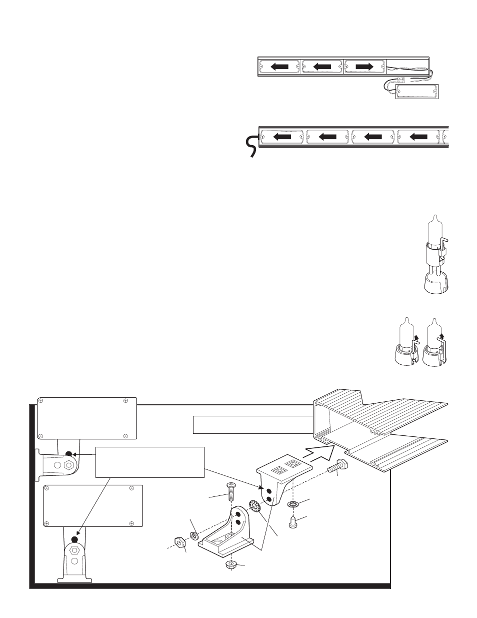
NOTE: Upper bracket of mounting feet slide inside
groove, and can be positioned to fit requirements.
NOTE: The mounting brackets feature 2
holes that can be used when assembling the
lower and upper brackets together to position
the light array assembly at 2 different heights.
Fig. 1
Mounting Foot Kit
1/4-20 X 7/16"
HEX NUT
1/4" SPLIT
LOCKWASHER
#14 X 1/2" PHILLIPS PH
"A" POINT SMS
#10-24 WHIZ NUT
1/4-20 X 3/4" HEX
HEAD SCREW
1/4" INTERNAL TOOTH
LOCK WASHER
MOUNTING
BRACKET
1/4" EXTERNAL TOOTH
LOCKWASHER
#10-24 X 1-1/4"
PPH MACHINE SCREW
(Item #1 on parts list)
Replacing a Halogen Snap-In Bulb:
WARNING: Replacing any bulb requires the use of
safety glasses to prevent injury. Do not handle the
bulb with bare hands.
WARNING: Replace lamps one at a time. If more
than one lamp is removed from the unit without
being replaced, the cable harness will shift and the
butt splices that connect the lightheads will be
inaccessible.
1.
Be sure the power to the lamp is off. Locate the removal
tool included with your new bulb and use the small end
of the tool to lift the base of the bulb assembly away
from the socket.
2.
Continue to lift until the bulb is free. Use either
of these illustrated methods, depending upon
application. Use a pliers to hold the tool and aid
bulb removal.
3.
Insert the alignment tab of the new bulb into
the bulb holder and press firmly into the
socket to lock the bulb into place.
Installation: Mounting the Traffic Advisor
CAUTION: Do not connect the T/A System to power until the
installation is completed. When servicing or troubleshooting
always disconnect it from the power source.
CAUTION: When the Traffic Advisor is mounted to the rear of
the vehicle, the cable exit must be on the passenger side. If
not, the flash pattern sequence you choose on the control
head will be incorrect. For example, a left flashing pattern will
flash right.
1.
Remove the two lower brackets of the mounting feet from the
mounting kit and secure them to the upper brackets with the supplied
hardware (Fig. 1).
2.
Slide mounting feet to their desired position inside the groove in the
extrusion and secure with supplied hardware.
3.
Loosen the hex nuts holding the upper and lower brackets together
and place the T/A in the desired position on the proposed mounting
surface. Adjust the lower brackets of the mounting feet to rest firmly
on the mounting surface and trace the outline of these brackets onto
that surface. If the T/A power cable is to pass through the mounting
surface, be sure to mark the area for this passage hole.
4.
Remove the T/A from the mounting surface and separate the lower
brackets of the mounting feet from the upper brackets. Align the
lower brackets with the outlines traced in the previous step and trace
the mounting hole locations onto the mounting surface. Make sure
that the lower bracket is facing in the same direction as it was
facing when it was outlined on the mounting surface in step 3.
5.
Examine the back side of the mounting surface to insure that no
damage will occur when drilling the mounting holes. Drill the
mounting holes with a 7/32” drill. If a wire passage hole has been
marked, drill the hole using a drill bit sized for the cable and a rubber
grommet (customer supplied).
6.
Secure the lower brackets to the mounting surface.
7.
Lower the T/A assembly onto the two lower brackets and secure both
brackets together with the supplied mounting hardware. Before
tightening the upper and lower brackets together, adjust the T/A to an
angle best suited to its mounting location.
8.
Slide the cable through the wire passage hole and route the cable to
the control head mounting location. Refer to your control head
manual for wiring.