Front view, Wiring the traffic advisor™ system, Installation: mounting control head – Whelen TA637A User Manual
Page 2
Page 2
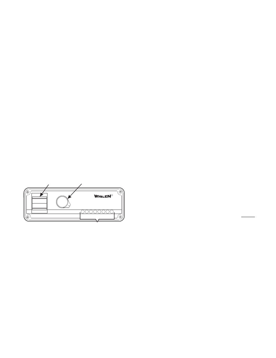
FRONT VIEW
LOW
HIGH
POWER
OFF
FLASH
SPLIT
RIGHT
LEFT
TRAFFIC ADVISOR
R
TM
FUNCTION
PATTERN SELECTION
ROTARY KNOB
HIGH / LOW / OFF
SWITCH
LED STATUS DISPLAY
DIRECTION INDICATOR
Important Note: This manual is used for both 12-volt and 24-
volt versions of TACTRL Series control head. All 24-volt
versions are identical to their 12-volt counterparts in both
function & operation. However, any fusing and wiring
differences will be documented in the appropriate sections.
The TACTRL Series Control Head features a four-function rotary
switch that allows the user to select from left arrow, right arrow,
split arrow, or flash pattern. Dip switches on the rear panel
determine which of the following patterns will be displayed when
“flash” is selected (see “Dip Switch Programming” on page 3).
•
One Lamp Sequence to TripleFlash™
•
One Lamp Sequence to DoubleFlash
•
Sequence to Solid
•
Solid Arrow
•
Two Lamp Sequences
•
Three Lamp Sequences
•
Four Lamp Sequences
•
Sequence On / Sequence Off
•
Remote Flash Control (TACTRL1A Only)
Remote Flash Control is the new feature on the TACTRL1A.
This allows for the remote activation of the flash function when
the T/A head is off. Turning on the control head overrides the
auxiliary control. This is ideal for activation with a slide switch
control.
2.
Drill the mounting holes in the areas scribed in step 1. The
size of the drill bit should be determined by the size of the
mounting hardware (customer supplied) and thickness of the
mounting surface.
3.
Using your mounting hardware, secure the bail strap to the
mounting location. NOTE: There are 2 sets of holes on the
bail strap for positioning the control head at 2 different
heights (see Page 3).
4.
With the bail strap in place, insert the carriage bolt along with
the external tooth lock washer (supplied) into the assembly
hole from the inner side of the Bail Strap as shown.
5.
Place the split lock washer and the acorn nut on the
protruding bolt on the outer side of the bail strap. Loosely
secure the acorn nut to the carriage bolt.
6.
Now slide the control head onto the carriage bolts. Once it is
in the position that the customer has chosen, tighten the
acorn nuts until the unit is firmly secured.
Wiring the Traffic Advisor™ System
1.
Plug the connector into the back of the control head unit (see
“Rear View” next page).
2.
Extend the RED and BLACK wires to the battery.
3.
Connect the RED wire to one end of a user supplied fuse
block. Do not connect this unit to the battery yet.
4.
Connect the BLACK wire to the vehicle’s chassis ground
5.
Extend and connect the WHITE wire to the accessory switch
for the back light controls (TACTRL1A only).
6.
Route the cable from the TA to the control head.
7.
Following the pin charts for your model on page 3, insert the
contact wires into their positions. Check that the wires are
fully inserted by pulling back on them firmly.
8.
Plug the connector(s) into the back of the control head.
WARNING! All customer supplied wires that connect to the
positive terminal of the battery must be sized to supply at
least 125% of the maximum operating current and FUSED at
the battery to carry that load. DO NOT USE CIRCUIT
BREAKERS WITH THIS PRODUCT!
(See “Wire Chart” on page 3)
The installation of your Traffic Advisor System will be complete
after the fuse block wire is connected to the POSITIVE (+)
terminal of the battery. After this connection has been made,
inspect the fuses at the control head and at the battery. If either of
these fuses are blown, carefully inspect all of the circuit wires and
make sure they are wired correctly. Replace blown fuses with one
of an identical amp rating as the original. If these fuses blow after
installation or activation, contact Whelen Engineering Technical
Support.
IMPORTANT! It is the responsibility of the installation
technician to make sure that the installation and operation of
this product will not interfere with or compromise the
operation or efficiency of any vehicle equipment! Before
returning the vehicle to active service, visually confirm the
proper operation of this product, as well as all vehicle
components/equipment.
A Center-Off Rocker Switch is used to turn the unit on and off, in
either high or low power mode. The TACTRL has an LED status
display that provides a visual indication of the current light
pattern.
Installation: Mounting Control Head
1.
Position the bail strap in the selected mounting location.
Using an awl or other suitable tool, scribe the surface where
the mounting hole are to be drilled.
Caution: Permanent mounting of this product will require
drilling. It is absolutely necessary to make sure that no other
vehicle components could be damaged by this process.
Check both sides of the mounting surface before starting. If
damage is likely, select a different mounting location.