Fig. 3, Fig. 1 fig. 2, Installation: mounting the traffic advisor – Whelen TA4437M User Manual
Page 2: Wiring, Servicing the light array, Halogen bulb replacement, Page 2
Page 2
MOUNTING SURFACE
MOUNTING
S
URF
ACE
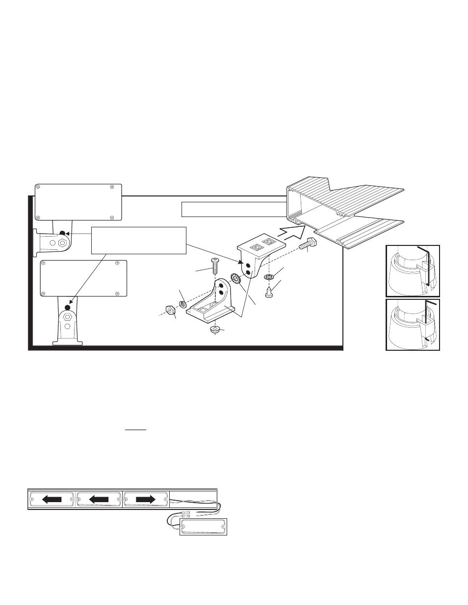
NOTE: Upper bracket of mounting feet slide inside
groove, and can be positioned to fit requirements.
NOTE: The mounting brackets feature 2
holes that can be used when assembling the
lower and upper brackets together to position
the light array assembly at 2 different heights.
1/4-20 X 7/16"
HEX NUT
1/4" SPLIT
LOCKWASHER
#14 X 1/2" PHILLIPS PH
"A" POINT SMS
#10-24 WHIZ NUT
1/4-20 X 3/4" HEX
HEAD SCREW
1/4" INTERNAL TOOTH
LOCK WASHER
MOUNTING
BRACKET
1/4" EX. TOOTH
LOCKWASHER
#10-24 X 1-1/4"
PPH MACHINE SCREW
Fig. 1
Fig. 2
4.
Remove the T/A from the mounting surface and separate the lower
brackets of the mounting feet from the upper brackets. Align the lower
brackets with the outlines traced in the previous step and trace the
mounting hole locations onto the mounting surface. Make sure that the
lower bracket is facing in the same direction as it was when it was
outlined on the mounting surface in step 3.
5.
Examine the back side of the mounting surface to insure that no damage
will occur when drilling the mounting holes. Drill the mounting holes with a
7/32” drill. If a wire passage hole has been marked, drill the hole using a
drill bit sized for the cable and a rubber grommet (customer supplied).
6.
Secure the lower brackets to the mounting surface.
7.
Lower the T/A assembly onto the two lower brackets and secure both
brackets together with the supplied mounting hardware. Before tightening
the upper and lower brackets together, adjust the T/A to an angle best
suited to its mounting location.
8.
Slide the cable through the wire passage hole and route the cable to the
control head mounting location. Refer to your control head manual for
wiring.
Installation: Mounting the Traffic Advisor™
Note: The mounting procedure shown here uses the optionally available
mounting kit. If this kit is not used, it is the customers responsibility to
determine the best mounting method/style for their specific application.
1.
Remove the two lower brackets of the mounting feet from the mounting kit
and secure them to the upper brackets with the supplied hardware (Fig.
1).
2.
Slide mounting feet to their desired position inside the groove in the
extrusion and secure with supplied hardware.
3.
Loosen the hex nuts holding the upper and lower brackets together and
place the T/A in the desired position on the proposed mounting surface.
Adjust the lower brackets of the mounting feet to rest firmly on the
mounting surface and trace the outline of these brackets onto that
surface. If the T/A power cable is to pass through the mounting surface,
be sure to mark the area for this passage hole.
Wiring:
CAUTION: Do not connect the T/A System to power until the installation
is completed. When servicing or troubleshooting always disconnect it
from the power source.
Refer to the wiring diagram on the last page and wire as shown.
WARNING! All customer supplied wires that connect to the positive
terminal of the battery must be sized to supply at least 125% of the
maximum operating current and FUSED at the battery to carry that
load. DO NOT USE CIRCUIT BREAKERS WITH THIS PRODUCT!
Servicing the Light Array:
1.
Disconnect the lightbar from the power source and remove the end cap
on the side that you wish to replace the lighthead.
2.
Slide the lighthead you wish to replace out of the base (Fig. 3).
3.
Cut the wires off of the old lighthead (removing the old butt splice).
Then, using a new butt splice, install the new lighthead then slide the
lighthead(s) back into the base.
NOTE: Replacing a lens or halogen bulb does not require
removing the lighthead.
Halogen Bulb Replacement:
1.
Remove the two lens screws and remove the lens.
CAUTION: To avoid personal injury, do not replace the lamp with your
fingers. Use the lamp replacement tool supplied with spare lamp kits.
CAUTION: Replacing any bulb requires the use of safety glasses. Do
not handle the bulb with bare hands. Use gloves.
2.
Be sure the power is turned off. Locate the removal tool included with
your new bulb. Use the small end of the tool to lift the base of the bulb
assembly away from the socket until the bulb is free. Use either of the
methods shown in Figure 2, depending upon application. Use a pliers to
hold the tool and aid bulb removal.
3.
Insert the alignment tab of the new bulb into the bulb holder and press
firmly into socket to lock the new bulb into place.
4.
Wipe any finger prints from the glass bulb with a soft cloth or tissue.
Replace lens and lens retaining screws.
Fig. 3
LAMP 1
LAMP 2
LAMP 3
Cut old lighthead from wire harness at butt
splice and install new lighthead with new butt splices.
LAMP 4