Fig. 3 endcap mounting bracket, Standard mounting kit fig. 1, Arrow end mounting kit fig. 2 – Whelen TA1252L User Manual
Page 2: Installation, Wiring
Page 2
Mounting
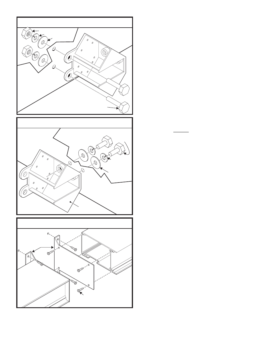
Bracket
#10 X 3/4"
PPHSMS
Fig. 3 Endcap Mounting Bracket
3/8" - 16 X 1" Hex Head Bolt
3/8" - 16 X 1" Hex Head Bolt
3/8" Split Lockwasher
3/8" Flatwasher
Mounting
Surface
Mounting
Surface
Standard Mounting Kit
Fig. 1
3/8" - 16 X 2"
Hex Head Bolt
Base
Casting
3/8" Split
Lockwasher
3/8" Flatwasher
Mounting
Surface
Mounting
Surface
Mounting
Surface
Arrow End Mounting Kit
Fig. 2
Mounting
Surface
Installation:
Install the T/A arrow light array as shown in Figures 1-3
depending on which mounting style you will use.
IMPORTANT: When you are routing any wires, the
existing, factory wire harness should be followed
whenever possible. The existing harness has been
carefully positioned so that the wires could not be
damaged by vehicle operation for example; if your
vehicle is equipped with a dump body, the harness is
positioned so that the dumping action will not crush
or pinch the wires. The factory harness may,
depending on vehicle design, include a service loop
that will keep the wires from being damaged or
broken by the movement of the dump body.
Wiring:
WARNING! All customer supplied wires that connect
to the positive terminal of the battery must be sized
to supply at least 125% of the maximum operating
current and FUSED at the battery to carry that load.
DO NOT USE CIRCUIT BREAKERS WITH THIS
PRODUCT!
Power Connector / P1
1.
Plug the power connector into the back of the control head
as shown in the wiring diagram.
Splice the 2 RED wires together, then extend this single RED
wire to the battery. Install a 30 amp fuse block (customer
supplied) to the end of the wire (remove the fuse before
connecting any wires to the battery) and connect it to the
POSITIVE (+) terminal on the battery.
IMPORTANT: There must not be more than 2 feet of
wire between the fuse block and the battery. The wire
between the fuse and battery is “unprotected”, don’t
allow this wire to come in contact with other wires.
2.
Splice the 2 BLACK wires together, then extend this single
BLACK wire to the battery and connect it to the battery
ground. If your vehicle has a cable extending from the
negative terminal of the battery to the chassis, it is best to
attach the black wire at the chassis connection.
Control Connectors / P2 & P3
1.
Route the control cables from the TA to the control head.
2.
Plug the connector(s) into the control head as shown.
3.
Refer to the control head manual for operation.
The installation of your system will be complete after the fuse
block wire is connected to the POSITIVE (+) terminal of the
battery. After this connection has been made, inspect the fuses
at the control head and at the battery. If either of these fuses are
blown, carefully inspect all of the circuit wires and make sure
they are wired correctly. Replace blown fuses with one of an
identical amp rating. If these fuses blow after installation or
activation, contact Whelen Engineering Technical Support.