Permanent mounting, Wiring, Scan-lock – Whelen R1LPPA User Manual
Page 2: Sync, Hi/low power, Pattern override, Permanent mounting / plastic base, Temporary mount (magnetic, suction cup, etc.), Page 2, Important warning
Page 2
CAUTION! DO NOT LOOK DIRECTLY AT THESE LEDS WHILE THEY ARE ON.
MOMENTARY BLINDNESS AND/OR EYE DAMAGE COULD RESULT!
IMPORTANT WARNING!
NOTE: The cigar cord adaptor
is equipped with an 8 Amp fuse.
Use a replacement fuse with an
identical value.
Switch Functions:
SW1 = ON/OFF
SW2 = Scan-Lock™ / Momentary
(12 volt model only)
IMPORTANT! The lightbar
should be a minimum of 16"
from any radio antennas!
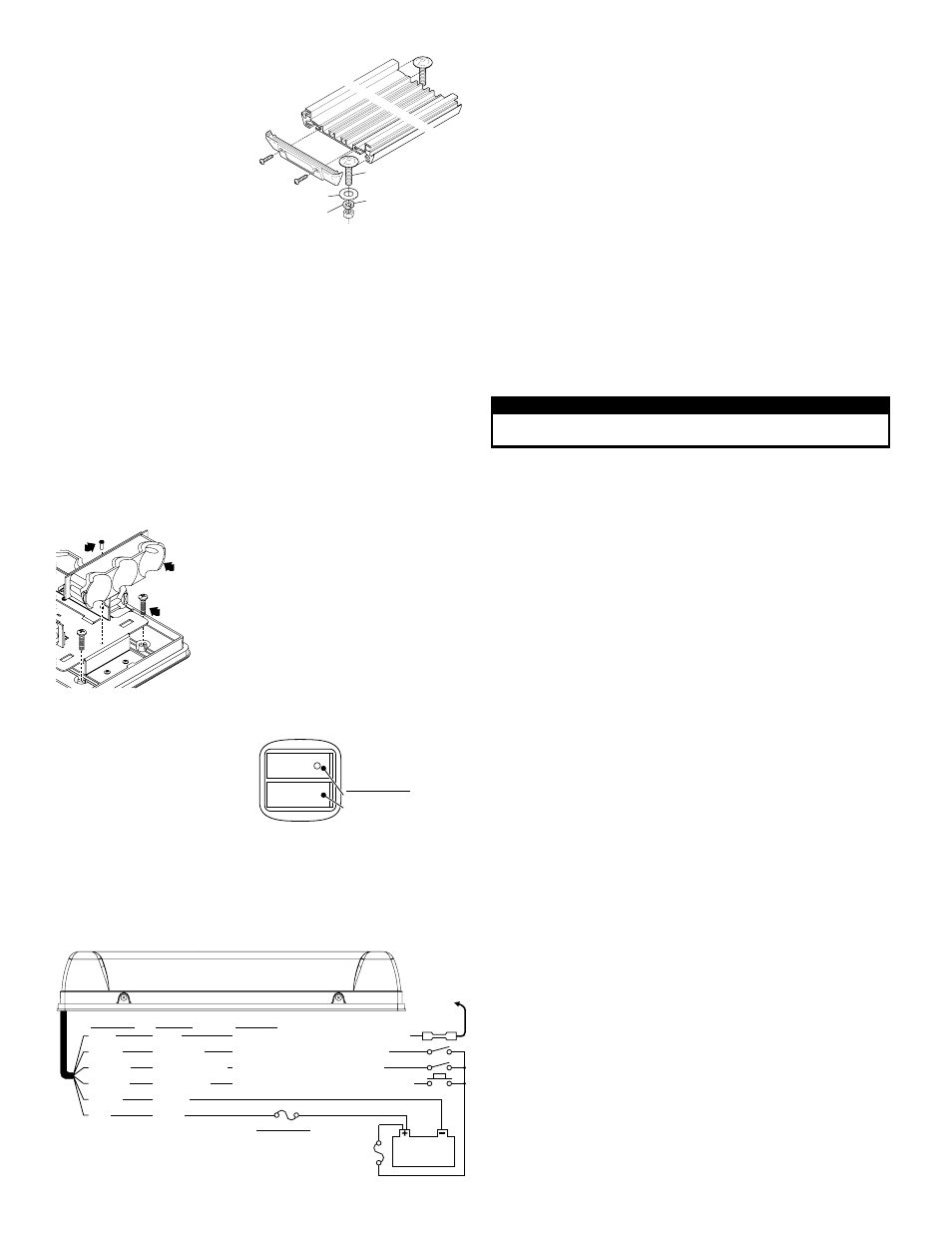
Permanent Mounting:
This mounting style requires removal of
the headliner. There may be a roof
support member that runs from the
drivers to the passengers side of the
vehicle. Do not drill through this
member.
Caution: Permanent mounting of this
product will require drilling. It is absolutely necessary to make sure that no
other vehicle components could be damaged by this process. Check both
sides of the mounting surface before starting. If damage is likely, select a
different mounting location.
1.
When the mounting location has been determined, slide the 2 mounting bolts
into the lightbar extrusion, one bolt in each track. Position these bolts so that
they are at opposite ends of the extrusion and as far appart as possible.
2.
Place the lightbar on the vehicle in its proposed mounting location. Mark the
location of the 2 mounting bolts onto the mounting surface. Also, mark the area
for the wire passage hole. This hole should be located directly below where the
wires exit the extrusion.
3.
Remove the lightbar and drill two, 5/16” dia. mounting holes and a 5/16” dia.
wire passage hole. De-burr all three holes and install a rubber grommet
(customer supplied) into the wire passage hole.
4.
Route the wires through the grommet and to the necessary switches and
power source as shown in the diagram below.
5.
Secure the Responder® to the vehicle using the hardware provided. From the
underside of the mounting surface, apply RTV around each mounting hole and
the grommeted wire passage hole to prevent water from entering these
openings.
Remove
one end
cap
3/8-16
HEX NUT
3/8" SPLIT
LOCK WASHER
3/8" FLAT
WASHER
3/8-16 X 1-1/4"
STEP BOLT
Available Flash Patterns:
1. ActionScan™
2. SignalAlert™ ALT
3. SignalAlert Sim)
4. SignalAlert (Alt/Sim)
5. CometFlash® (Alt)
6. CometFlash (Sim)
7. CometFlash (Alt-Sim)
8. DoubleFlash 75 (Alt)
9. DoubleFlash 75 (Sim)
10.DoubleFlash 75 (Alt-Sim)
11.SingleFlash 75 (Alt)
12.SingleFlash 75 (Sim)
13.SingleFlash 75 (Alt-Sim)
14.LongBurst™ (Alt)
15.LongBurst (Sim)
16.LongBurst (Alt-Sim)
17.SingleFlash 60 (Alt) CA
18.SingleFlash. 60 (Sim) CA
19.SingleFl. 60 (Alt-Sim) CA
20.SingleFlash 90 (Alt) CA
21.SingleFlash 90 (Sim) CA
22.SingleFl. 90 (Alt-Sim) CA
23.SingleFlash 120 (Alt) CA
24.SingleFlash 120 (Sim) CA
25.SingleFl. 120(Alt-Sim) CA
26.SingleFlash 240 (Alt)
27.SingleFlash 240 (Sim)
28.SingleFlash 240 (Alt-Sim)
29.MicroBurst™ (Alt)
30.MicroBurst (Sim)
31.MicroBurst (Alt-Sim)
32.ActionFlash™ (Alt)
33.ActionFlash (Sim)
34.ActionFlash (Alt-Sim)
35.PingPong™
36.FlimFlam (Alt.)
37.ModuFlash™ (Alt)
38.ModuFlash (Sim)
39.Steady 2.5%
40. Steady 4%
41.Steady 6%
42.Steady 8%
43.Steady 12%
44.Steady 40%
45.InOut
46.Sweep
47.LongBurst Sweep
48.InOut Blast
49.Sequence On/Off
50.ZigZag
51.Rotator 90
52.Rotator 120
53.Rotator 150
54.Rotator 250
CA = Calif. Title XIII Compliant Alt = Alternating Sim = Simultaneous Alt-Sim = Alternating-Simultaneous
= SYNC
*
*
*
*
*
*
*
*
*
Wiring:
WARNING! All customer supplied wires that connect to the positive terminal of
the battery must be sized to supply at least 125% of the maximum operating
current and FUSED at the battery to carry the load. DO NOT USE CIRCUIT
BREAKERS WITH THIS PRODUCT!
Scan-Lock™:
To operate Scan-Lock, switch the lightbar on. The Scan-Lock wire will be either
WHT/VIO or WHT (See wiring) Magnetic and Suction mount models use a
momentary switch on the cigar plug instead of a wire (12 volt only).
TO CHANGE PATTERNS: To cycle forward to the next pattern apply +VBAT to the
Scan-Lock wire (or switch) for less than 1 second and release. To cycle back to the
previous pattern apply +VBAT to Scan-Lock™ wire for over 1 second and release.
TO CHANGE THE DEFAULT PATTERN: When the desired pattern is displayed,
allow it to run for more than 5 seconds. The lighthead will now display this pattern
when initially activated.
TO RESTORE THE FACTORY DEFAULT PATTERN: With power off, apply +VBAT
to the Scan-Lock™ wire (or switch). While continuing to apply power to Scan-Lock
turn lighthead(s) on. The factory default pattern will be displayed.
A Normally Open momentary switch can be used to control Scan-Lock. See
below for available flash patterns.
Sync:
To SYNC two lightbars, configure both lightbars to display the same flash pattern.
With the power off, connect the GREY wire from each lightbar together. When the
lightbars are activated, their patterns will be synchronized. Only the flash patterns
designated for SYNC in the flash pattern list may be used.
Hi/Low Power:
Allows user to step the unit down to low power for nighttime use.
Latching Mode: By applying +VBAT to the VIOLET wire for less than 1 second, the
lightbar is “latched” into low power. The unit must be turned off and then back on to
restore normal high power operation (Momentary switch).
Level Mode: Applying +VBAT to the VIOLET wire for more than 1 second holds the
lightbar in low power mode until voltage is removed (Toggle switch).
Pattern Override:
Applying +VBAT to the ORANGE wire while lightheads are activated, will change the
flash pattern to whatever pattern override is programmed for. To program the flash
pattern activate the lightbar then activate pattern override by applying +VBAT to the
ORANGE wire and select a flash pattern using Scan-Lock.
IMPORTANT! It is the responsibility of the installation technician to make sure
that the installation and operation of this product will not interfere with or
compromise the operation or efficiency of any vehicle equipment! Before
returning the vehicle to active service, visually confirm the proper operation of
this product, as well as all vehicle components/equipment.
Permanent Mounting / Plastic Base
Remove
screw
Lift lighthead
out to access
mounting
screws.
1.
2.
3.
4.
5
Remove the outer dome and the screws that hold
down the endcap lightheads
lightheads out.
Install the #10 screws into the 4 mounting holes
to open up the holes.
Remove the screws, position the base on the
proposed mounting location then scribe the
mounting surface where the mounting holes are
to be drilled.
Remove the base and drill the 4 mounting holes
using a #
drill
.
Install the lightbar. Replace the lightheads & dome.
(use a T-10 TORX bit)
and lift the (2)
16
bit
.
1.
1.
.
.
.
.
.
2
3
3
3
4
Temporary Mount (Magnetic, Suction Cup, etc.):
WARNING: The use of any
magnetically mounted warning
device on the outside of a vehicle in
motion is not recommended and is at
the sole risk and responsibility of the
user.
Magnetic/suction: Thoroughly clean
the proposed mounting surface prior to
mounting. For suction cup mounting, wipe the suction cup clean, place the beacon
onto its mounting surface and apply gentle pressure to ensure a good seal has been
achieved. The Magnetic/Suction Cups mount the same way as standard suction
cups but are best suited to a flat, steel surface. Magnetic: Place lightbar onto the
mounting surface and plug it into the vehicle cigar lighter.
GREY
SYNC
Networks with other SYNC-capable lights
Apply +VBATT for Low Power mode
Apply +VBATT for Pattern Override
Flash Pattern Selection (see pattern list)
Low Power
Pattern Override
Scan-Lock™
Ground
Power
VIOLET
ORANGE
WHT/VIO
BLACK
RED
Connect to
GREY SYNC
wire from
a n o t h e r
SYNC light
24 Volt Models
R1LP***
R2LPH***
- 5A
- 5A
- 7.5A
Wire Color
Function
Operation
BUTT SPLICE
1A
Fuse
12 24
V / V
Battery
Responder® LP
NOTE:
All fuses and switches
are customer supplied
Wiring Diagram:
All models except R2LPQH (See page 3)
Fuse Values