Permanent mounting, Temporary mount (optional), Wiring – Whelen R2HDPA User Manual
Page 2: Operation, Wht/vio - scan-lock™ / flash pattern selection, Grey - sync, Violet - hi/low power, Orange - pattern override
Page 2
IMPORTANT! The lightbar should be located a minimum of
16" from any radio antennas!
Permanent Mounting:
First check to see that no vehicle components will interfere with the
selected mounting location. If you are installing the lightbar on the roof you
will need to remove the headliner from the vehicle. There may be a roof
support member that runs from the drivers to the passengers side of the
vehicle. Do not drill through this member. The mounting bolts can slide the
length of the bar, however you should keep them as close to the outer
edges of the bar as possible for stability. They must be on opposite
corners of the base.
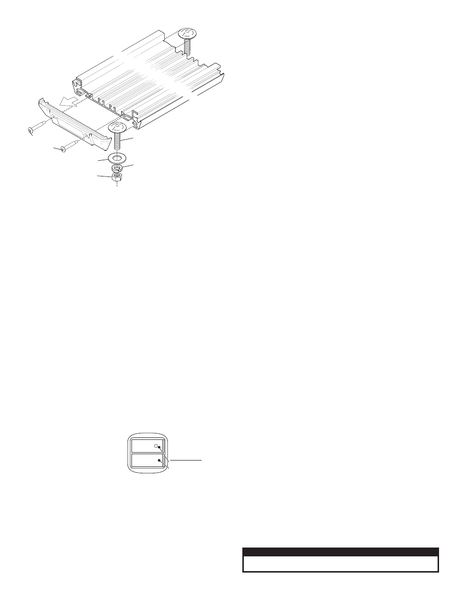
1.
When you have determined the mounting location, remove one of
the endcaps from the lightbar. Slide the two bolts in as shown then
hold the lightbar onto the vehicle and mark the location of the 2
mounting holes onto the mounting surface.
2.
Drill the 2 mounting holes using a drill bit sized for a 5/16” hole.
3.
Replace the end cap then insert the mounting bolts into the
mounting holes and secure them onto the lightbar with the mounting
hardware as shown.
4.
Cut a 5/16” hole for the lightbar cable, install a rubber grommet
(customer supplied) to protect the cable then insert the cable onto
the wire hole and connect to power.
Temporary Mount (Optional)
WARNING: The use of any magnetically mounted warning device on
the outside of a vehicle in motion is not recommended and is at the
sole risk and responsibility of the user.
Magnetic/suction: Thoroughly
clean the proposed mounting
surface prior to mounting. For
suction cup mounting, wipe the
suction cup clean, place the
beacon onto its mounting surface
and apply gentle pressure to
ensure a good seal has been achieved. The Magnetic/Suction Cups
mount the same way as standard suction cups but are best suited to a flat,
steel surface. Magnetic: Place the beacon onto the mounting surface and
plug it into the vehicle cigar lighter.
Wiring:
WARNING! All customer supplied wires that connect to the positive
terminal of the battery must be sized to supply at least 125% of the
maximum operating current and FUSED at the battery to carry the
load. DO NOT USE CIRCUIT BREAKERS WITH THIS PRODUCT!
NOTE: See wiring diagrams on parts pages for wiring and fusing.
NOTE: The cigar cord adaptor
is equipped with an 8 Amp fuse.
Use a replacement fuse with an
identical value.
Switch Functions:
SW1 = ON/OFF
SW2 = Scan-Lock™ / Momentary
Operation:
R2HD** / Rotator Model:
Applying +12 volts to the RED wire activates
the lightbar and rotators. No features are available for this lightbar.
R9HDM* / R9HDV* / R10HDM* / R10HDV* / Linear TIR™ & GEN
III Models:
Plug cigar cord into vehicle lighter and turn the cigar plug
switch on to activate the lightbar. Pressing the Scan-Lock™ cigar cord
switch activates Scan-Lock™ flash pattern selection.
R9HDP* / R10HDP* / Linear TIR & GEN III Models:
Applying + 12
volts to the RED wire activates the lightbar. Refer to the wiring diagrams
for functions for your model.
WHT/VIO - Scan-Lock™ / Flash Pattern Selection:
To operate Scan-Lock™ switch the lightbar on. Cigar plug models have
a momentary switch next to the on/off switch on the cigar plug.
Permanent mount models have a Scan-Lock™ function wire.
TO CHANGE PATTERNS: To cycle forward to the next available pattern
apply +12 volts to the WHT/VIO wire (Or press the momentary switch on
the cigar plug) for less than 1 second and release.
To cycle back to the previous pattern apply +12 volts to the WHT/VIO wire
(Or press the momentary switch) for more than 1 second and release.
TO CHANGE THE DEFAULT PATTERN: When the desired pattern is
displayed, allow it to run for more than 5 seconds. The lightbar will now
display this pattern when initially activated.
TO RESTORE THE FACTORY DEFAULT PATTERN: With power to the
lightbar off, apply +12 volts to the WHT/VIO wire (Or press and hold the
momentary switch). With power applied to Scan-Lock™, turn power to the
lightbar on. The factory default pattern will be displayed.
A normally open momentary switch can be used to control Scan-
Lock™ operation.
NOTE: The features listed below apply to R10HDP* only.
GREY - Sync:
To SYNC two lightbars, configure both lightbars to display the same flash
pattern. With the power off, connect the GREY wire from each lightbar
together. When the lightbars are activated, their patterns will be
synchronized. Only the flash patterns designated for SYNC in the flash
pattern list may be used.
NOTE: Refer to parts pages for available flash pattern lists.
VIOLET - Hi/Low Power:
Allows user to step the unit down to low power for nighttime use.
Latching Mode: By applying +VBAT to the VIOLET wire for less than 1
second, the lightbar is “latched” into low power. The unit must be turned off
and then back on to restore normal operation (Momentary switch).
Level Mode: Applying +VBAT to the VIOLET wire for more than 1 second
keeps the lightbar in low power until voltage is removed (Toggle switch).
ORANGE - Pattern Override:
Applying +VBAT to the ORANGE wire while lightheads are activated, will
change the flash pattern to whatever pattern override is programmed for.
To program the flash pattern activate the lightbar then activate pattern
override by applying +VBAT to the ORANGE wire and select a flash
pattern using Scan-Lock™.
IMPORTANT! Before returning this vehicle to active service, visually
confirm the proper operation of this product, as well as all vehicle
components/equipment.
Caution: Permanent mounting of this product will require drilling. It
is absolutely necessary to make sure that no other vehicle
components could be damaged by this process. Check both sides of
the mounting surface before starting. If damage is likely, select a
different mounting location.
CAUTION! DO NOT LOOK DIRECTLY AT THESE LEDS WHILE THEY ARE ON.
MOMENTARY BLINDNESS AND/OR EYE DAMAGE COULD RESULT!
IMPORTANT WARNING!
Remove
one end
cap
3/8-16
HEX NUT
3/8" SPLIT
LOCK WASHER
3/8" FLAT
WASHER
10-24 X 1.25"
TX PHD
SWADGE
3/8-16 X 1-1/4"
STEP BOLT