Wiring, Scan-lock, Hi/low control – Whelen FT8AAAAP User Manual
Page 4
Page 4
Corners / Cross
Corners / Alternating
Wiring:
The cigarette plug model plugs into your cigarette lighter and requires no
further wiring.
If your lightbar has an 11-conductor cable, refer to the chart below for
important wiring information.
NOTE: See internal fuse replacement information on next page.
WARNING! All customer supplied wires that connect to the positive
terminal of the battery must be sized to supply at least 125% of the
maximum operating current and FUSED at the battery to carry that
load. DO NOT USE CIRCUIT BREAKERS WITH THIS PRODUCT!
Scan-Lock™:
To cycle forward through all patterns: Apply power to the control wire
of the function you want to change, then apply power to the BLACK-
YELLOW (Scan-Lock™) wire for less than 1 second and release. This will
change the pattern. Repeat for next pattern.
To choose a pattern: While cycling through the patterns, when you find
the pattern you want let it run for more than 5 seconds and it will lock in
and become the default pattern.
To reset to the factory default pattern: Turn off power, apply power to
the Scan-Lock™ wire and the wire of the function you want to reset, then
turn power back on.
Scan-Lock™ can be connected to a customer supplied SPST switch.
CAUTION: Permanent mounting will require drilling. The installer must be
sure that no vehicle components or other vital parts will be damaged. Be
aware of the location of any front, side or upper air bags.
CAUTION: There may be a roof support member that spans the distance
between the driver’s and passenger’s side. Do not drill through this
member. Adjust the location of the cable access hole until the hole can be
drilled without contacting this support member.
IMPORTANT! It is the responsibility of the installation technician to make
sure that the installation and operation of this product will not interfere with
or compromise the operation or efficiency of any vehicle equipment!
CAUTION: Using a magnetic mounted light on the outside of a vehicle, while in motion, is not recommended and is at the sole risk of the user.
Installation:
1.
To protect the headliner from damage caused by drilling the cable access hole through the vehicle roof, allow a 5” to 7” distance between roof and
headliner by lowering the headliner before drilling.
2.
Using a 1” hole saw, drill the cable access hole. Use a round file to smooth and de-burr the edges and insert a 1” grommet (user supplied).
3.
Insert the cable(s) through the cable access hole into the vehicle. Use RTV silicone to weatherproof the access hole after the cable(s) are pulled into
the vehicle.
4.
When routing the cable(s), be sure to use a path that avoids any vehicle components or other vital parts that may be damaged. Also be careful not to
interfere with any vehicle air bags (front, side, etc.). Route the cable(s) towards your switch panel and refer to the instructions included with the
switch panel for wiring information.
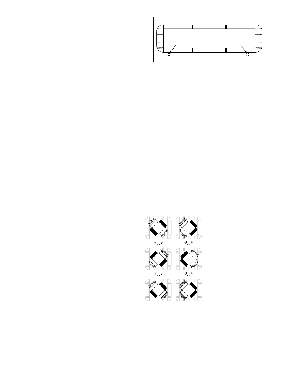
DRILLING THE CABLE ACCESS HOLE
Drill cable access hole in appropriate area
for your lightbar (see note)
FRONT OF LIGHTBAR
For
cables exiting
the Driver-side
of the extrusion
lightbars
with
For
cables exiting
the Passenger-side
of the extrusion
lightbars
with
Hi/Low Control:
The type of switch used is dependant on how the operator wishes
the Hi/Low feature to function:
Option 1: Latching Mode: By applying +voltage to the VIOLET wire for
less than 1 sec., the power supply is “latched” into low power operation.
The unit must be turned off and then back on to restore normal, Hi power
operation. A momentary switch is best for this method.
Option 2: Level Mode: Applying +voltage to the VIOLET wire for more
than 1 sec. holds the power supply in low power mode until that voltage is
removed. A toggle switch is best for this method.
Color / Voltage
Function
Fuse @
RED / +12VDC .....................LED Flasher (+) Positive ............ 5 Amps
BLK-YEL / +12VDC .............Scan-Lock™ .................................1 Amp
GRY / +12VDC.....................Front Corner LEDs ........................1Amp
WHT / +12VDC ....................Halogen 1 (Optional) .................. 5 Amps
WHT-BLK / +12VDC............Inboard LEDs ............................. 5 Amps
YEL / +12VDC......................Halogen 2 (Optional) .................. 5 Amps
WHT-BLU / +12VDC............Rear Corner LEDs (Optional) .......1 Amp
BLK-WHT / Ground ............Halogen 1 & 2 (-) Ground (Optional) N/A
WHT-VIO / +12VDC .............Endcap LEDs ...............................1 Amp
VIO / +12VDC ......................Low Power....................................1 Amp
BLK / Ground ......................LED Flasher (-) Ground.................... N/A
NOTE: The available flash patterns are
shown here. This will show how FRONT
LEDs (optional) and CORNER LEDs react
to Alternating and Cross flash patterns.
Available Flash Patterns:
1A SignalAlert™..................... Alternating
1B SignalAlert™............................. Cross
1C SignalAlert™........... 3 of 1A & 3 of 1B
2A CometFlash®.................... Alternating
2B CometFlash®............................ Cross
2C CometFlash®.......... 3 of 2A & 3 of 2B
3A DoubleFlash ..................... Alternating
3B DoubleFlash ............................. Cross
3C DoubleFlash ........... 3 of 3A & 3 of 3B
4A SingleFlash....................... Alternating
4B SingleFlash............................... Cross
4C SingleFlash............. 3 of 4A & 3 of 4B
5 Steady Flash .........1 & 2 Steady;3 & 4
SingleFlash (SIM)
6 Steady ................................ All Steady