Servicin our li htbar g y g, Wiring diagram, Wiring – Whelen LT2AAAAP User Manual
Page 4: Scan-lock, Hi/low control, Page 4, Available flash patterns
Page 4
With
Alley
Light
#6 x 5/8" PPH
PLAST-LOC
Without
Alley
Light
#6-32 x 5/8"
PPHMS
#6-32 ELASTIC
STOP NUT
Servicin
our Li htbar
g y
g
Installing Corner Linear-LED®
Lighthead into extrusion
Insert the tabs on the lighthead housing,
into the channels in the extrusion.
Insert the tabs on the lighthead housing,
into the channels in the extrusion.
Installing Lens and Lighthead
Housing into extrusion
Lens
fits
here
Top and bottom of extrusion
secure to Support Bracket.
SUPPORT
BRACKET
Installing a lighthead
into its housing
Use the illustrations shown if you
need to gain access to the lightbar
to service or replace parts.
10
500 HALO. #1
WHITE
BLACK
Front of Lightbar (4 Light Shown)
48
A
B
Replace
fuse
here
Replace
fuse
here
Replace
fuse
here
FUSE
10
AMP
500 LED #1
BLUE
WHT/BRN
WHITE
BLACK
500 HALO. #1
500 LED #4
BLUE
WHT/YEL
YELLOW
BLACK
500 HALOGEN #2
CORNER LED #3
GREEN
WHT/ORG
CORNER LED #2
GREEN
WHT/RED
500 LED #3
GREEN
WHT/ORG
BLUE
WHT/BRN
CORNER LED #1
BLUE
WHT/YLW
CORNER LED #4
GREEN
WHT/RED
500 LED #2
YELLOW
BLACK
500 HALOGEN #2
44
46
45
47
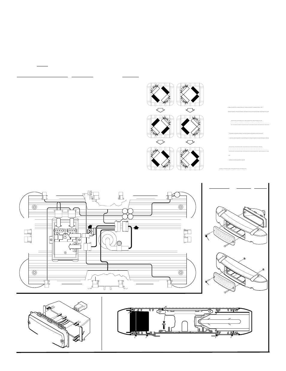
Wiring Diagram
Available Flash Patterns:
NOTE: The available flash patterns are
shown here. This will show how FRONT
LEDs (optional) and CORNER LEDs
react to Alternating and Cross flash patterns.
1A
B
C
2A
B
C
3A
B
C
4A
B
C
6
7
SignalAlert™
CometFlash
DoubleFlash
SingleFlash
SteadyFlash
Steady
1
1
2
2
3
3
4
4
SignalAlert™
SignalAlert™
CometFlash
CometFlash
DoubleFlash
DoubleFlash
SingleFlash
SingleFlash
®
®
®
Alternating
Cross
3 cycles of 1A & 3 cycles of 1B
Alternating
Cross
3 cycles of 1A & 3 cycles of 1B
Alternating
Cross
3 cycles of 1A & 3 cycles of 1B
Alternating
Cross
3 cycles of 1A & 3 cycles of 1B
1 & 2 Steady 3 & 4
SingleFlash (SIM.)
1, 2, 3 & 4 Steady
Corners / Cross Corners / Alternating
Wiring:
The cigarette plug model plugs it into your cigarette lighter and requires no further
wiring.
If you have a lightbar that has an 11-conductor cable, refer to the chart below for
important wiring information.
NOTE: For internal fuse replacement see information on next page.
WARNING! All customer supplied wires that connect to the positive terminal of
the battery must be sized to supply at least 125% of the maximum operating
current and FUSED at the battery to carry that load. DO NOT USE CIRCUIT
BREAKERS WITH THIS PRODUCT!
Scan-Lock™:
To cycle forward through all patterns: Apply power to the control wire of the
function you want to change, then apply power to the BLK/YEL (Scan-Lock™) wire
for less than 1 second and release. This will change the pattern. Repeat for next
pattern.
To choose a pattern: While cycling through the patterns, when you find the pattern
you want let it run for more than 5 seconds and it will lock in and become the default
pattern.
To reset to the factory default pattern: Turn off power. While applying power to the
Scan-Lock™ wire, turn power on to the light(s) you want to reset.
Scan-Lock can be connected to a customer supplied SPST switch.
Hi/Low Control:
Option 1: Latching Mode: By applying +voltage to the VIOLET wire for less than 1
sec., the power supply is “latched” into Low power operation. The unit must be turned
off and then back on to restore normal, Hi power operation. A momentary switch is
best for this method.
Option 2: Level Mode: Applying +voltage to the VIOLET wire for more than 1 sec.
holds the power supply in Low power mode until that voltage is removed. A toggle
switch is best for this method.
WIRE COLOR (VOLTAGE) FUNCTION
FUSE @
RED (+12VDC) . . . . . . . . . . .LED Flasher (+) Positive . . 5 Amps
BLK / YEL (+12VDC) . . . . . .Scan-Lock™. . . . . . . . . . . . . 1 Amp
GRY (+12VDC) . . . . . . . . . . .Front Corner LEDs . . . . . . . . 1 Amp
WHT (+12VDC). . . . . . . . . . .Halogen 1. . . . . . . . . . . . . . 5 Amps
WHT/BLK (+12VDC) . . . . . .Inboard LEDs . . . . . . . . . . . 5 Amps
YEL (+12VDC) . . . . . . . . . . .Halogen 2. . . . . . . . . . . . . . 5 Amps
WHT / BLU (+12VDC) . . . . .Rear Corner LEDs . . . . . . . . 1 Amp
BLK / WHT (-) . . . . . . . . . . . .Halogen 1 & 2 Ground . . . . . . . N/A
WHT / VIO (+12VDC) . . . . . .Endcap LEDs . . . . . . . . . . . . 1 Amp
VIO (+12VDC). . . . . . . . . . . .Low Power . . . . . . . . . . . . . . 1 Amp
BLK (-) . . . . . . . . . . . . . . . . .LED Flasher (-) Negative . . . . . N/A