Wiring, Connecting the cables, Power cable – Whelen FN55VLED User Manual
Page 4: Control cable, White-violet / scan-lock, Violet / low power
Page 4
Wiring:
1.
To protect the headliner from damage caused by drilling the
cable access hole through the vehicle roof, allow a 5” to 7”
distance between the roof and the headliner by lowering the
headliner before drilling.
WARNING! There is a roof support member that spans
the distance between the driver’s and
passenger’s side. DO NOT DRILL THROUGH
THIS MEMBER! Adjust the location until the
hole can be drilled without contacting this
support member.
Refer to “Safety First” on Page 1 for
important precautionary information.
2.
Using a 1” hole saw, drill the cable access hole.
3.
Use a round file to de-burr the edges of the cable access hole
and insert a 1” grommet (customer supplied) into the hole.
4.
Insert the cables through the cable access hole into the
vehicle. Use RTV silicone to weatherproof the access hole
after the cables are pulled completely into the vehicle.
5.
Route the cables one at a time to your power source. It is left
to the installation technician’s discretion where to run the
cables, as vehicles will vary.
Connecting the Cables:
WARNING! All customer supplied wires that connect to
the positive terminal of the battery must be sized to
supply at least 125% of the maximum operating current
and FUSED at the battery to carry that load. DO NOT
USE CIRCUIT BREAKERS WITH THIS PRODUCT!
Power Cable:
1.
Route the power cable towards the firewall. Again the
wires
path is left to the installation technician’s discretion.
2.
Follow the factory wiring harness through the firewall. It may
be necessary to drill a hole in the firewall. If so, be absolutely
sure that there are no components that could be damaged by
drilling. Insert a grommet into the hole, to protect the cable.
1.
Route the cable along the factory wiring harness towards the
battery.
2.
Install a 40 Amp fuse block (customer supplied) on the end of
the RED wire in the power cable. Remove the fuse from the
fuse block before connecting any wires to the battery.
3.
Connect the fuse block to the POSITIVE (+) terminal on the
battery. There can not be more than two (2) feet of wire
between the fuse block and the battery. The wire between
the fuse block and the battery is “unprotected”, do not allow
this wire to come into contact with any other wires.
4.
Connect the BLACK wire to the factory chassis ground
adjacent to the battery.
Control Cable:
Extend the control cable to your switch panel and make the
appropriate connections, using the information provided on page 3.
When you apply +12 VDC to a Control Cable wire, you activate its
function. The control cable connects to your control head or switch
box and is fused there. Typical fusing is 5 Amps.
Note: The wire functions listed in this manual are the
factory default settings for a fully loaded lightbar.
To find the correct wire functions for the lightbar
you ordered, refer to the switch operations sheet
included with your lightbar.
White-Violet / Scan-Lock™
TO CYCLE FORWARD THROUGH ALL PATTERNS: Choose the
Scan-Lock™ wire controlling the function you wish to change the
flash pattern on and apply +12 volts to that wire for less than 1
second and release. This will change the pattern. Repeat to go to
next pattern.
TO CHOOSE A PATTERN: While cycling through the patterns,
when you find the pattern you want let it run for more than 5
seconds and it will lock in and become the default pattern.
TO RESET TO THE FACTORY DEFAULT PATTERN: Turn off the
option you want to reset, apply +12 volts to the Scan-Lock function
wire of that option then turn the option back on.
Available LED Scan-Lock™ Patterns: SignalAlert™ 75 (Default
pattern) / CometFlash® 75 / DoubleFlash 150 / DoubleFlash 75 /
SingleFlash 375 / SingleFlash 150 / SingleFlash 75 / ActionFlash™
75 / ModuFlash™ 75 / ActionScan™
Front Inboards only: Single 75, Driver Steady / 2 Lamps Steady
Violet / Low Power
The type of switch used is dependant on how the operator wishes
the Hi/Low feature to function:
Latching Mode: By applying +12 VDC voltage to the Violet wire for
less than 1 sec., the power supply is “latched” into low power
operation. The unit must be turned off and then back on to restore
normal, Hi power operation. (A Momentary Switch is Preferred)
Level Mode: Applying +12 VDC voltage to the Violet wire for more
than 1 sec. holds the power supply in low power mode until voltage
is removed. (A Toggle Switch is Preferred)
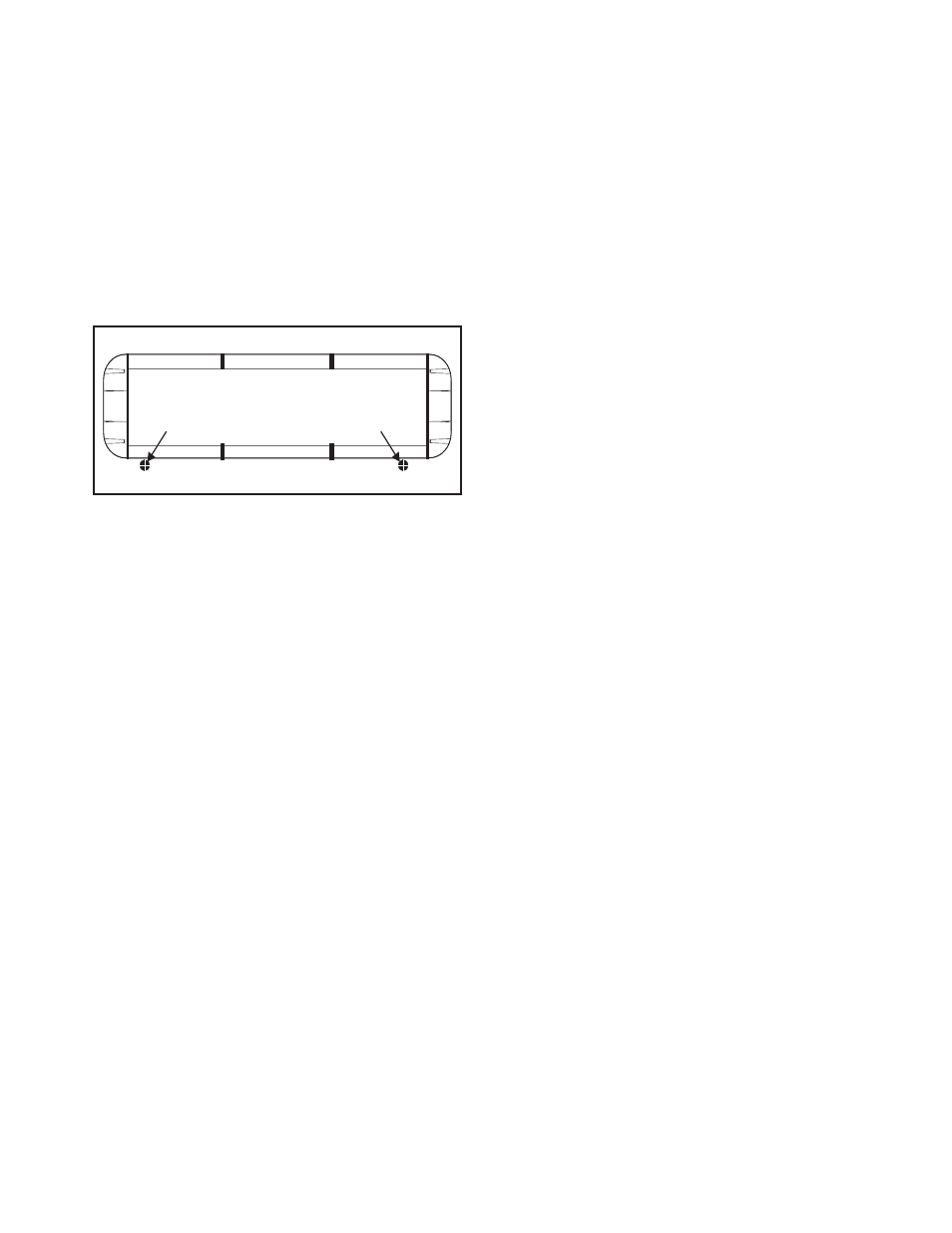
DRILLING THE CABLE ACCESS HOLE
Drill cable access hole in appropriate area
for your lightbar (see note)
FRONT OF LIGHTBAR
For
cables exiting
the Driver-side
of the extrusion
lightbars
with
For
cables exiting
the Passenger-side
of the extrusion
lightbars
with