Fig. 2, Fig. 1, Page 2 – Whelen IX37UF5P User Manual
Page 2: Installation / standard, Installation / caprice, Wiring, Operation, Wiring diagram
Page 2
10 X 1" PHILLIPS
PAN HD SHEET
METAL SCREW
(type A) (QTY 1)
#8-32 x 3/8 TORX HD
SCREW (QTY 2)
VISOR
SWIVEL
BRACKET
VISOR CLIP BRACKET
Fig. 2
SHEET METAL
HEADLINER
VISOR CLIP
MOUNTING
BRACKET
SHEET
METAL
ROOF
RUBBER
SEAL
Lightbar
Side View
WIND
SHIE
LD
Side View
IMPORTANT! The lightbar should be a minimum of 16" from radio antennas!
When routing wires, choose a path that will keep wires away from excessive
heat or any vehicle equipment that could damage the wires.
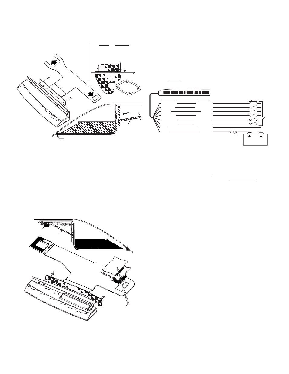
Installation / Standard:
1. Loosen (do not remove) the three screws securing the passenger-side visor
swivel bracket to the vehicle.
2. Remove screws securing vehicles visor clip and remove clip and hardware.
3. Secure the bracket to the Inner Edge housing using hardware provided (Fig. 1).
4. Position the keyed opening of the mounting bracket directly under the location of
the visor clip removed in step 2 and remount the visor clip in its original location
using the original hardware (Fig. 1).
5. Firmly tighten any hardware loosened in this procedure.
6. Repeat this procedure for the driver-side assembly.
7. When properly mounted, the rubber seal will be in full contact with the vehicle
windshield and roof. This is to prevent light output from entering the passenger
compartment. When this has been achieved, tighten mounting hardware firmly.
8. Route the lightbar cable down the vehicle A-pillar to your control head. Make all
wiring connections using the information in the wiring diagram.
Installation / Caprice:
1. Secure
the mounting
bracket to the
Inner Edge housing
using the two
#8 - 32 X 3/8 TORX HEAD
SCREWS provided (Fig. 2).
2. Loosen (do not remove) the screws securing the passenger-side visor swivel
bracket to the vehicle.
3. Slide the outside end of the mounting bracket under the visor swivel bracket (Fig.
2). At the same time slip the rectangular hole in the other end of the mounting
bracket over the visor clip bracket. With the mounting bracket in position retighten
the visor swivel bracket hardware.
4. Using the screw hole in the mounting bracket as a guide, drill a pilot hole into the
sheet metal behind the headliner and secure other side of mounting bracket using
the supplied #10 X 1” PHILLIPS PAN HEAD SHEET METAL SCREW.
5. Repeat this procedure for the driver-side assembly.
6. When properly mounted, the rubber seal will be in full contact with the vehicle
windshield and roof. This is to prevent light from entering the passenger
compartment. When this has been achieved, tighten all mounting hardware firmly
to maintain contact.
7. Route the lightbar cable down the vehicle A-pillar to your control head and make
all wiring connections using the information in the wiring diagram.
Wiring:
WARNING! All customer supplied wires that connect to the positive terminal of
the battery must be sized to supply at least 125% of the maximum operating
current and FUSED at the battery to carry that load. DO NOT USE CIRCUIT
BREAKERS WITH THIS PRODUCT!
Operation:
8-conductor cable. All functions listed here may not be present in all lightbars.
WHITE/GREEN - Scan-Lock™
The WHT/GRN wire allows you to choose from a variety of flash patterns. A
light must be activated to change the pattern.
TO CYCLE THROUGH ALL PATTERNS: To cycle forward apply +12 VDC to the
WHT/GRN wire for less than 1 second and release. To cycle backward apply +12
VDC to the WHT/GRN wire for more than 1 second and release.
TO SET A PATTERN AS DEFAULT: When the pattern is displayed, allow it to run for
more than 5 seconds. The lighthead will now display this pattern when active.
TO RESET TO THE FACTORY DEFAULT PATTERN: Turn off power and apply +12
VDC to the WHT/GRN wire while turning power on.
A normally open momentary switch is best suited for Scan-Lock operation.
BLUE: Flash 1
Apply +12 VDC to the BLUE wire to activate the warning lights. Fuse wire @ 1 Amp.
BROWN: Hi/Low Power
This feature allows you to run the lightbar in low power for night time use. Fuse wire
@ 1 Amp. A single pole / single throw switch can be used to control Hi/Low power.
To activate Low power: Apply +12 VDC to the BRN wire. To restore regular
power: Remove the BRN wire from +12 VDC.
WHITE/BLACK: Take-Downs
Apply +12 VDC to the WHT/BLK wire to activate the take-downs. Fuse this wire @ 1
Amp. 5 light models only.
WHITE/ORANGE: Flashing Take-Down
Apply +12VDC to the WHT/ORG wire to activate flashing take-down mode. Fuse this
wire @ 1 Amp. Note: The WHT/BLK wire overrides this display. 5 light models.
ORANGE: California Steady
Apply +12 VDC to the ORG wire to activate lightheads using the California Steady
pattern table (next page). Refer to the following page for lighthead identification.
Fuse wire @ 1 Amp. NOTE: Due to firmware requirements, there are several
‘null’ patterns (no lighthead active) that precede Pattern 1. Repeated Scan-
Lock activations may be required before Pattern 1 selection is achieved.
Wiring Diagram
To
+12VDC
(fuse ea. @ 1A
WHT/GRN
BROWN
BLUE
ORANGE
WHT/BLK
WHT/ORG
BLK
RED
Scan-Lock
Low Power
Flash 1
CA Steady
Take-Downs
Flashing T-D
Ground (-)
+12VDC
All Fuses & Switches Customer Supplied
Fuse
(5 Amp)
Wire Color
Function
Momentary Switch
SPST Switch
SPST Switch
SPST Switch
SPST Switch
SPST Switch
BATTERY
Available Flash Patterns:
1. ActionScan™
2. SignalAlert™ 75 Alternating
3. SignalAlert™ 75 Multi.
4. CometFlash® 75 Alternating
5. CometFlash® 75 Multi.
6. DoubleFlash 75 Alternating
7. DoubleFlash 75 Multi.
8. SingleFlash 75 Alternating
9. SingleFlash 75 Multi.
10. LongBurst™ 75 Alternating
11. LongBurst™ 75 Multi.
12. SingleFlash 60 Alternating
13. SingleFlash 60 Multi.
14. SingleFlash 90 Alternating
15. SingleFlash 90 Multi.
16. SingleFlash 120 Alternating
17. SingleFlash 120 Multi.
18. ‘SingleFlash 240 Alternating
19. SingleFlash 240 Multi.
20. DoubleFlash 120 Alternating
21. DoubleFlash120 Multi.
22. ActionFlash™ 75 Alt.
23. ActionFlash™ 75 Multi.
24. ActionFlash™ 150 Alt.
25. ActionFlash™ 150 Multi.
26. MicroBurst™ Alternating
27. MicroBurst™ Multi.
28. PingPong™ Alternating
29. PingPong™ Multi.
30. FlimFlam Alternating
31. FlimFlam Multi.
32. ModuFlash™ Alternating
33. ModuFlash™ Multi
34. Cylon 1
35. Cylon 2
36. Cylon Chaser
37. Eyeballs Sync
38. Eyeballs In/Out
39. 2 Eyeballs In/Out
40. Eyeballs Crazy
Mounting
Bracket
ROOF
#8-32 x 3/8 Torx
Hd Screw (QTY 2)
RUBBER SEAL
Lightbar
Side View
Lightbar
Side View
Lightbar
Side View
WI
ND
SH
IEL
D
Fig. 1
HEADLINER
VISOR CLIP
side view
VISOR CLIP
side view
RETAINER
RETAINER
The
&
have a
retainer to hold the headliner to
the visor clip, which must be
removed before remounting
the visor clip.
Tahoe
Silverado
NOTE: An Explorer mounting bracket is
shown here. The bracket for your vehicle
may be shaped differently but the basic
shape and mounting will be the same.
PA
SSENGER
SIDE
Under
visor
swivel bracket
Under
visor
clip
VISOR CLIP
side view