Fig. 1, Installation 2013 ford fusion, Fig. 2 fig. 4 – Whelen IX43UFX User Manual
Page 2: Fig. 5, Fig. 3
Page 2
DRIVER SIDE DOOR
Pry plastic
cover off
VISOR SWIVEL
BRACKET
WINDSHIELD
Remove screw
and visor clip
VISOR
CLIP
MOUNTING CLIP
(remove)
V
IS
O
R
Fig. 1
WINDSHIELD
Installation 2013 Ford Fusion:
IMPORTANT AIR BAG WARNING! Do not install this product or route
any wires in the deployment area of your air bag. Equipment
mounted or located in the air bag deployment area will damage or
reduce the effectiveness of the air bag, or become a projectile that
could cause serious personal injury or death. Refer to your vehicle
owners manual for the air bag deployment area. The User/ Installer
assumes full responsibility to determine proper mounting location,
based on providing ultimate safety to all passengers.
IMPORTANT! The lightbar should be located a minimum of 16" from
any radio antennas!
Note: When routing the wires, it is important to choose a path that
will keep the wires away from excessive heat or any vehicle
equipment that could compromise the integrity of the wires (ex.
trunk lids, door jams, etc.)
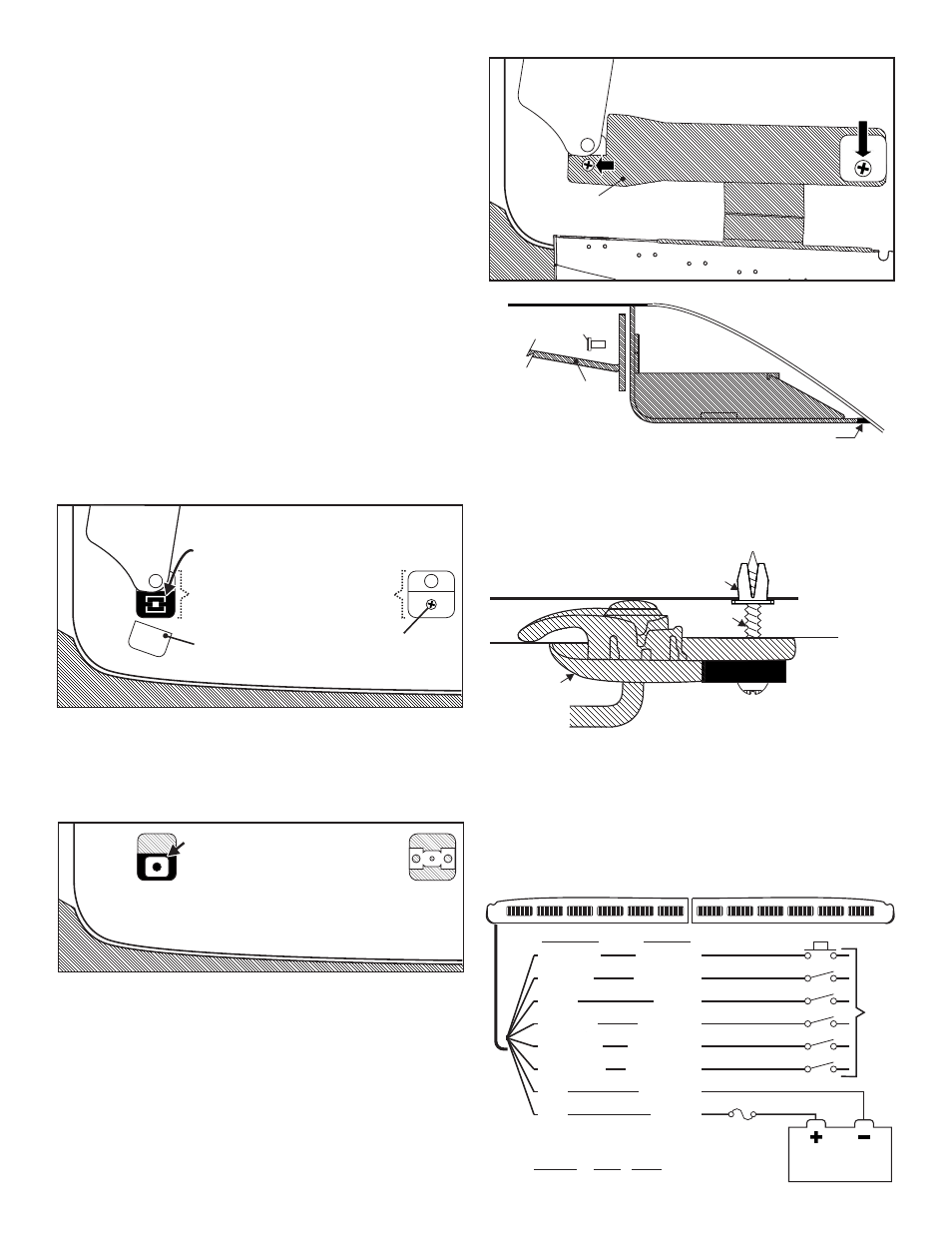
Figures 1 thru 3 show the driver side of the interior of the vehicle, shown
looking up at the roof.
1.
On the driver side visor swivel bracket, carefully pry the plastic cover
off of the front of the bracket (Fig. 1). The lightbar mounting bracket
will sit in the space that the cover occupied. NOTE: Pry the cover
off using two flat blade screwdrivers on each side to avoid
braking the cover. The cover will not be used here but should be
saved in case you wish to remove the lightbar in the future.
2.
Remove the swivel bracket mounting clip (located under the cover
you removed in step 1) and lift the swivel bracket assembly out.
Install the supplied fastex grommet into the hole in the roof sheet
metal which the clip snapped into. Reinsert the swivel bracket
assembly (Figs. 1 & 2).
3.
On the vehicle visor clip, remove the screw holding on the clip and
remove the clip. The supplied #8 X 1" sheet metal screw will replace
the screw you removed (Fig. 2).
4.
Secure the mounting bracket to the lightbar and position the bracket
where it will mount on the vehicle (Figs. 3 & 4).
5.
Secure the lightbar bracket to the swivel mount using the supplied 1/
4 X 1-1/4” Phillips Pan Head Sheet Metal Screw. This screw will
thread into the fastex grommet you installed in step 2 and the bracket
will sit where the cover was (Fig. 5).
6.
Line the rectangular hole in the other end of the lightbar bracket, up
with the visor clip and install the visor clip over the lightbar bracket
using the supplied #8 X 1” Sheet Metal Screw (Fig. 3).
7.
Make sure all mounting hardware is tightened firmly and repeat
procedure for the passenger side of the vehicle.
8.
Extend the cables and connect to power. Refer to the lightbar manual
for wiring and fusing information.
Wiring:
Install Faston grommet
into existing hole in roof
that clip snapped into.
Fig. 2
Fig. 4
When properly mounted, the rubber seal should be in full
contact with the vehicle windshield. The rear of the lightbar
should be in contact with the roof. This is to prevent light
from entering the passenger compartment. When this has
been achieved, tighten mounting hardware firmly to
maintain contact.
Mounting
Bracket
ROOF
#8-32 x 3/8 Torx Hd
Screw (QTY 2)
WIN
DSH
IEL
D
RUBBER SEAL
Lightbar
Side View
Lightbar
Side View
Lightbar
Side View
Fig. 5
ROOF SHEET METAL
SCREW
GROMMET
HEADLINER
V I S O R
S W I V E L
BRACKET
LT BAR BRACKET
MOUNTING TAB
Re-install visor clip over bracket
using supplied #8 X 1" sheet metal screw
Install into Faston grommet using
supplied 1/4 X 1-1/4" PPHSMS
Install into Faston grommet using
supplied 1/4 X 1-1/4" PPHSMS
Install into Faston grommet using
supplied 1/4 X 1-1/4" PPHSMS
MOUNTING
B R AC KE T
Fig. 3
Wirin
Dia ram
g
g
To
+12VDC
(fuse ea. @ 1A
WHT/GRN
BROWN
BLUE
ORANGE
WHT/BLK
*
WHT/ORG
*
BLK
RED
Scan-Lock
Low Power
Flash 1
CA Steady
Take-Downs
Flashing T-D
Ground (-)
+12VDC
All Fuses & Switches
Customer Supplied
*
Not used with 12 light models
Fuse
(5 Amp)
Wire Color
Function
Momentary Switch
SPST Switch
SPST Switch
SPST Switch
SPST Switch
SPST Switch
BATTERY