Wirin dia ram g g, Fig. 1, Installation – Whelen IX13UFZ User Manual
Page 2: Wiring, Operation, Battery
Page 2
IMPORTANT! The lightbar should be located a minimum of 16" from
any radio antennas!
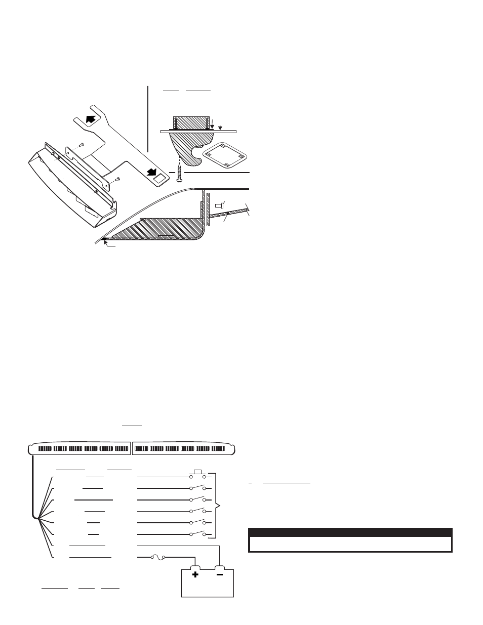
Installation:
Note: When routing wires, it is important to choose a path that will keep
the wires away from excessive heat or any vehicle equipment that could
compromise the integrity of the wires (ex. trunk lids, door jams, etc.)
1. Using a screwdriver, loosen (do not remove) the three screws securing the
passenger-side visor swivel bracket to the vehicle.
(See reference to
retainer in Figure 1)
2. Remove the screws securing the visor clip to the vehicle. Remove and retain
the clip and all hardware.
3. Secure the bracket to the Inner Edge housing using the hardware provided.
4. Position the keyed opening of the mounting bracket directly under the
mounting location for the visor clip. With the bracket in this position, remount
the visor clip in its original location using the original hardware (Fig. 1).
5. Firmly tighten any hardware loosened in this procedure.
6. Repeat this procedure for the driver-side assembly.
7. When properly mounted, the rubber seal will be in full contact with the
vehicle windshield and roof. This is to prevent light output from entering the
passenger compartment. When this has been achieved, tighten mounting
hardware firmly to maintain contact (Fig. 1).
8. Route the lightbar cable down the vehicle A-pillar to your control head.
9. Make all wiring connections using the information in the wiring diagram.
Wiring:
WARNING! All customer supplied wires that connect to the positive
terminal of the battery must be sized to supply at least 125% of the
maximum operating current and FUSED at the battery to carry that load.
DO NOT USE CIRCUIT BREAKERS WITH THIS PRODUCT!
Operation:
This lightbar is powered and controlled by an 8-conductor cable exiting
the lightbar. All functions listed here are not present in all lightbars.
White/Green - Scan-Lock™
The WHITE/GREEN wire allows you to choose from the available flash
patterns. First you must activate the lighthead(s) you wish to change:
TO CYCLE THROUGH ALL PATTERNS: To cycle forward apply +12 VDC
to the WHT/GRN wire for less than 1 second and release. to cycle
backward apply +12 VDC to the WHT/GRN wire for more than 1 second
and release.
TO SET A PATTERN AS DEFAULT: When the pattern is displayed, allow it
to run for over 5 seconds. The lighthead will now display this pattern when
active.
TO RESET TO THE FACTORY DEFAULT PATTERN: Turn off power and
apply +12 VDC to the WHT/GRN wire while turning power on.
A normally open momentary switch is best used for Scan-Lock
operation.
Blue: Flash 1
Apply +12 VDC to the BLU wire to activate the warning lights. Fuse this wire
@ 1 Amp.
Brown: Hi/Low Power
The low power feature allows you to step the lightbar down to run in low
power for night time use. Fuse this wire @ 1 Amp. An SPST switch can be
used to control Hi/Low power. To activate Low power operation: Apply
+12 VDC to the BRN wire. To restore regular power: Remove voltage from
the BRN wire.
White/Black: Take-Downs
Apply +12 VDC to the WHT/BLK wire to activate the take-downs. Fuse this wire
@ 1 Amp. NOTE: Not used with 12 Light models.
White/Orange: Flashing Take-Down
Apply +12VDC to the WHT/ORG wire to activate flashing take-down mode.
Fuse this wire @ 1 Amp. Note: The WHT/BLK wire overrides this display.
NOTE: Not used with 12 Light models.
Orange: California Steady
Apply +12 VDC to the ORG wire to activate lightheads using the California
Steady pattern table. Refer to the artwork on the following page for lighthead
identification. Fuse this wire @ 1 Amp.
IMPORTANT! Before returning this vehicle to active service, visually
confirm the proper operation of this product, as well as all vehicle
components/equipment.
California Steady Pattern Table:
#
Active Lightheads
1.
D1
2.
D2
3.
D3
4.
D4
5.
D5
6.
D6 (12-Light Models Only)
7.
D1 + P1
8.
D2 + P2
9.
D3 + P3
10.
D4 + P4
11.
D5 + P5
12.
D6 + P6 (12-Light Models Only)
Wirin
Dia ram
g
g
To
+12VDC
(fuse ea. @ 1A
WHT/GRN
BROWN
BLUE
ORANGE
WHT/BLK
*
WHT/ORG
*
BLK
RED
Scan-Lock
Low Power
Flash 1
CA Steady
Take-Downs
Flashing T-D
Ground (-)
+12VDC
All Fuses & Switches
Customer Supplied
*
Not used with 12 light models
Fuse
(5 Amp)
Wire Color
Function
Momentary Switch
SPST Switch
SPST Switch
SPST Switch
SPST Switch
SPST Switch
BATTERY
CAUTION! DO NOT LOOK DIRECTLY AT THESE LED’S WHILE THEY ARE ON.
MOMENTARY BLINDNESS AND/OR EYE DAMAGE COULD RESULT!
I M P O R TA N T W A R N I N G !
NOTE: An Explorer mounting bracket is
shown here. The bracket for your vehicle
may be shaped differently but the basic
shape and mounting will be the same.
Mounting
Bracket
ROOF
#8-32 x 3/8 Torx
Hd Screw (QTY 2)
RUBBER SEAL
Lightbar
Side View
Lightbar
Side View
Lightbar
Side View
WI
ND
SH
IEL
D
PA
SSENGER
SIDE
Fig. 1
HEADLINER
VISOR CLIP
side view
VISOR CLIP
side view
RETAINER
RETAINER
The
&
have a retainer
which holds the headliner to the visor
clip. Remove the retainer before you
remount the visor clip.
Tahoe
Silverado
Under
visor
swivel bracket
Under
visor
clip
VISOR CLIP
side view
Available Flash Patterns:
1. ActionScan™
2. SignalAlert™ 75 Alternating
3. SignalAlert™ 75 Multi.
4. CometFlash® 75 Alternating
5. CometFlash® 75 Multi.
6. DoubleFlash 75 Alternating
7. DoubleFlash 75 Multi.
8. SingleFlash 75 Alternating
9. SingleFlash 75 Multi.
10. LongBurst™ 75 Alternating
11. LongBurst™ 75 Multi.
12. SingleFlash 60 Alternating
13. SingleFlash 60 Multi.
14. SingleFlash 90 Alternating
15. SingleFlash 90 Multi.
16. SingleFlash 120 Alternating
17. SingleFlash 120 Multi.
18. ‘SingleFlash 240 Alternating
19. SingleFlash 240 Multi.
20. DoubleFlash 120 Alternating
21. DoubleFlash120 Multi.
22. ActionFlash™ 75 Alt.
23. ActionFlash™ 75 Multi.
24. ActionFlash™ 150 Alt.
25. ActionFlash™ 150 Multi.
26. MicroBurst™ Alternating
27. MicroBurst™ Multi.
28. PingPong™ Alternating
29. PingPong™ Multi.
30. FlimFlam Alternating
31. FlimFlam Multi.
32. ModuFlash™ Alternating
33. ModuFlash™ Multi
34. Cylon 1
35. Cylon 2
36. Cylon Chaser
37. Eyeballs Sync
38. Eyeballs In/Out
39. 2 Eyeballs In/Out
40. Eyeballs Crazy