Fig. 1, Usb port, Installation – Whelen IW37UF6P User Manual
Page 2: Connecting the power cable, Connecting the communication cable, Control point module, Programming procedure, Page 2, Passenger side shown, Side view
Page 2
10 X 1" PHILLIPS PAN
HD SHEET METAL SCREW
(type A) (QTY 1)
#8-32 x 3/8 TORX HD SCREW (QTY 2)
VISOR SWIVEL
BRACKET
Passenger Side Shown
VISOR
CLIP
MOUNTING
BRACKET
SHEET
METAL
ROOF
RUBBER SEAL
Lightbar
Side View
WI
ND
SH
IEL
D
VISOR CLIP BRACKET
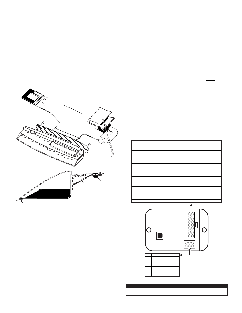
Fig. 1
SHEET METAL
Slip over visor
clip bracket
Slide under visor
swivel bracket
Side View
HEADLINER
IMPORTANT! Before mounting this unit refer to the AIR BAG
WARNING on page 1. Read all warnings before beginning.
IMPORTANT! The lightbar should be located a minimum of 16" from
any radio antennas!
Installation:
Note: When routing wires, it is important to choose a path that will keep
the wires away from excessive heat or any vehicle equipment that could
compromise the integrity of the wires (ex. trunk lids, door jams, etc.)
1. Secure the mounting bracket to the Inner Edge housing using the two
#8 - 32 X 3/8 TORX HEAD SCREWS provided (Fig. 1).
2. Loosen (do not remove) the screws securing the passenger-side visor swivel
bracket to the vehicle.
3. Slide the outside end of the mounting bracket under the visor swivel bracket
(Fig. 1). At the same time slip the rectangular hole in the other end of the
mounting bracket over the visor clip bracket (Fig. 1). With the mounting
bracket in position retighten the visor swivel bracket hardware.
4. Using the screw hole in the mounting bracket as a guide, carefully drill a pilot
hole (for a #10 sheet metal screw) into the sheet metal
behind the headliner and secure the other side of
the mounting bracket using the
supplied #10 X 1” PHILLIPS PAN
HEAD
SHEET METAL SCREW.
5. Repeat this procedure for the driver-side assembly.
6. When properly mounted, the rubber seal will be in full contact with the
vehicle windshield and roof. This is to prevent light output from entering the
passenger compartment. When this has been achieved, tighten all mounting
hardware firmly to maintain contact (Fig. 1).
7. Route the lightbar cable down the vehicle A-pillar to your control head.
8. Make all wiring connections using the information in the wiring diagram.
Connecting the Power Cable:
WARNING! All customer supplied wires that connect to the positive
terminal of the battery must be sized to supply at least 125% of the
maximum operating current and FUSED at the battery to carry that load.
DO NOT USE CIRCUIT BREAKERS WITH THIS PRODUCT!
1. Follow the factory wiring harness through the firewall. It may be necessary to
drill a hole in the firewall. If so, be absolutely sure that there are no
components that could be damaged by drilling. After the hole has been
drilled, insert a grommet to protect the cable.
2. Route the cable along the factory wiring harness towards the battery. Install
a 40 amp fuse block (customer supplied) on the end of the RED wire in the
power cable. NOTE: Remove the fuse from the fuse block before
connecting any wires to the battery.
3. Connect the BLACK wire to Chassis Ground.
Connecting the Communication Cable:
Splice the GREEN and GREY wires from the lightbar to the GREEN and GREY
wires from the Whelen WC Controller.
Control Point Module
The Control Point Module serves as the ‘brains’ of the Whelen WC Series
lightbar. The module is programmed with the WeCan™ Programming Software
via the USB port and in turn, provides the necessary signals that allow the
lightbar to function in the desired manner.
Each of the 18 inputs in WeCan™ Programming software may be
programmed to activate any number or combination of installed lightbar
components by applying +12VDC to an input. Refer to the installation
guide included with your switches for detailed wiring information.
Programming Procedure:
IMPORTANT - It is not necessary to program this device unless changes
to the default configuration (for example pattern or switch control
changes) are desired.
1. Connect a USB cable from the host PC to the module’s USB port.
2. Start the WeCan software on the host PC and open the configuration to be
programmed.
3. Click on the “WeCan” button on the menu bar. Select “Control Point” then
“Program” from the fly-out.
4. A window will open to confirm that you are about to program a Control Point
Module. Confirm that the USB cable is connected to both the module and the
PC and then press “OK” to continue. The software will display a window
when the programming procedure has been successfully completed.
5. Confirm proper operation of the module.
DEFAULT CONFIGURATION (12V Inputs)
COLOR
GREEN
GRN/WHT
GRN/BLK
WHT/RED
WHITE
YELLOW
WHT/VIO
WHT/GRN
WHT/ORG
BLUE
BLU/WHT
BLU/BLK
WHT/BRN
WHT/BLK
WHT/BLU
RED/WHT
WHT/YEL
VIOLET
*
*
ALTERNATING DRIVER-PASSENGER (SignalAlert™ 75)
DRIVER OUTBOARD DUO (STEADY)
PASSENGER OUTBOARD DUO (STEADY)
DRIVER INBOARD (CA STEADY)
OUTBOARD DUO (SingleFlash 150)
CRUISE LIGHTS
CA BAR PATTERN
ULTRA SCAN BAR PATTERN
CA SINGLE
ZZ CA 75 BAR PATTERN
CENTER DUO (STEADY)
ALTERNATING SIDE-TO-SIDE DUO (DoubleFlash 75)
LOW POWER
ALL DUO (STEADY)
ALTERNATING SIDE-TO-SIDE (SignalAlert™ 75)
IN-OUT (SignalAlert™ 75)
ALTERNATING DRIVER-PASSENGER (ASYNC) (SignalAlert™ 75)
ULTRA SCAN BAR PATTERN
CENTER DUO (SingleFlash 150)
FUNCTION
POS
1
2
3
4
5
6
7
8
9
10
11
12
13
14
15
16
17
18
Connect to an ignition controlled
circuit that can accommodate an
additional 250mA load.
from lightbar
1
2
Lightbar
Cable
Connector
2
1
2
2
COLOR
RED
None
BLACK
GREEN
BLK/WHT
GREY
FUNCTION
+12VDC
GROUND
COMM. A
SHIELD
COMM. B
POS
1
2
3
4
5
6
USB
Port
18 9
17 8
16 7
15 6
14 5
13 4
12 3
11 2
10 1
1
4
2
5
3
6
CAUTION! DO NOT LOOK DIRECTLY AT THESE LED’S WHILE THEY ARE ON.
MOMENTARY BLINDNESS AND/OR EYE DAMAGE COULD RESULT!
I M P O R TA N T W A R N I N G !