Usb port, Connecting the communication cable, Control point module – Whelen IW43UF6P User Manual
Page 3: Programming procedure, Troubleshooting, Page 3
Page 3
Connecting the Communication Cable:
Splice the GREEN and GREY wires from the lightbar to the GREEN and
GREY wires from the Whelen WC Controller.
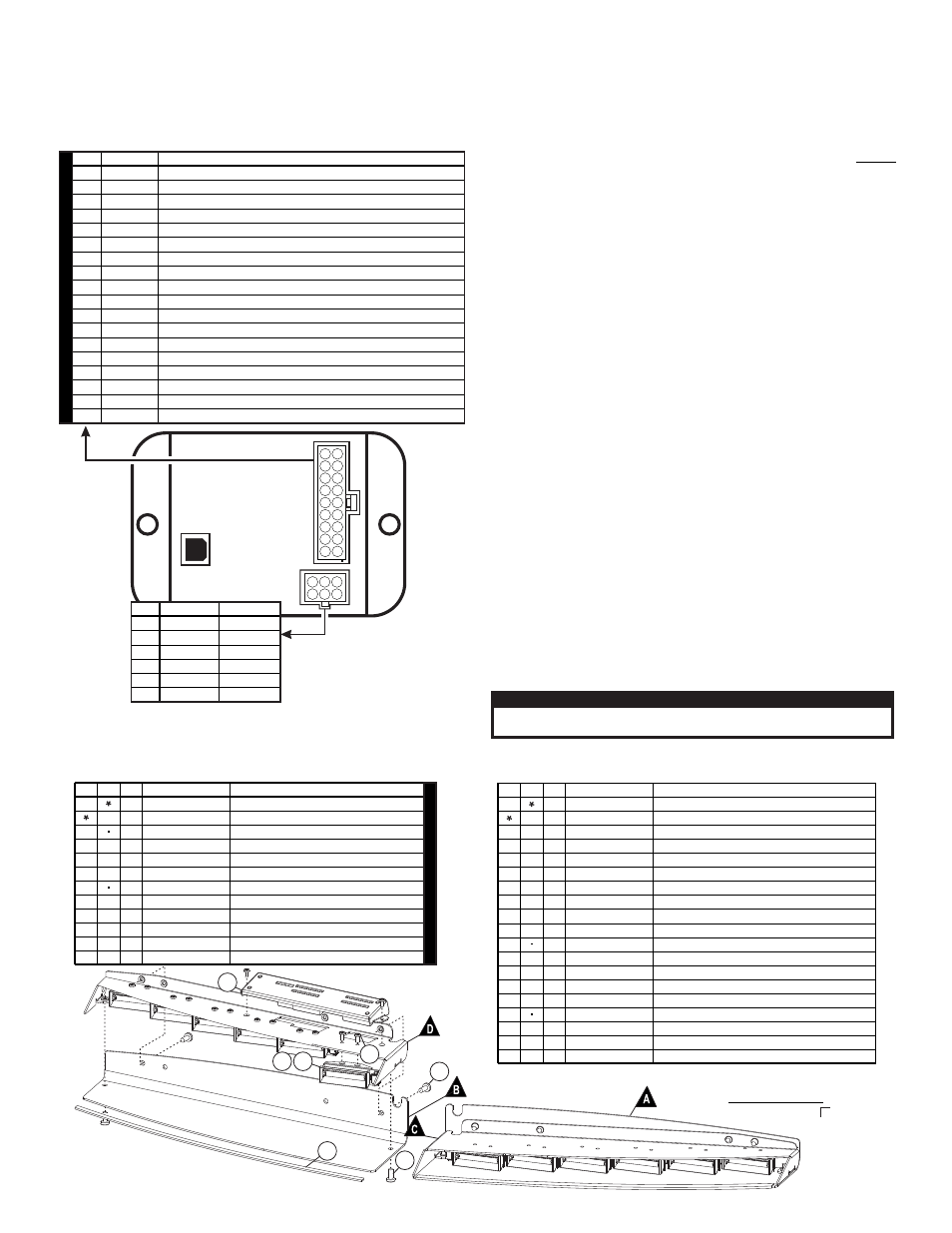
Control Point Module:
The Control Point Module serves as the ‘brains’ of the Whelen WC Series
lightbar. The module is programmed with the WeCan™ Programming
Software via the USB port and in turn, provides the necessary signals that
allow the lightbar to function in the desired manner.
Each of the 18 inputs in WeCan™ Programming software may be
programmed to activate any number or combination of installed lightbar
components by applying +12VDC to an input. Refer to the installation
guide included with your switches for detailed wiring information.
Programming Procedure:
IMPORTANT - It is not necessary to program this device unless
changes to the default configuration (for example pattern or switch
control changes) are desired.
1.
Connect a USB cable from the host PC to the module’s USB port.
2.
Start the WeCan software on the host PC and open the configuration
to be programmed.
3.
Click on the WeCan button on the menu bar. Select “Control Point”
then “Program” from the fly-out.
4.
A window will open to confirm that you are about to program a
Control Point Module. Confirm that the USB cable is connected to
both the module and the PC and then press “OK” to continue. The
software will display a window when the programming procedure has
been successfully completed.
5.
Confirm proper operation of the module.
Troubleshooting:
Your lightbar should now be fully operational. If it is not functioning
properly, check your connections for the following:
•
The positive wire (RED) is properly connected to the battery, by
way of the user supplied fuse block.
•
A working fuse of the correct amperage is installed in the fuse
block (See illustration above, for the specific fuse rating for
your lightbar).
•
The ground wire (BLACK) is properly connected to the factory
ground. Be sure that the wire is fully grounded to this location.
•
The two communication wires (GREEN and GREY) are properly
connected to their communication designations.
If these connections are good, contact your Whelen® representative for
further assistance.
IMPORTANT! Before returning this vehicle to active service, visually
confirm the proper operation of this product, as well as all vehicle
components/equipment.
CAUTION! DO NOT LOOK DIRECTLY AT THESE LED’S WHILE THEY ARE ON.
MOMENTARY BLINDNESS AND/OR EYE DAMAGE COULD RESULT!
I M P O R TA N T W A R N I N G !
COLOR
GREEN
GRN/WHT
GRN/BLK
WHT/RED
WHITE
YELLOW
WHT/VIO
WHT/GRN
WHT/ORG
BLUE
BLU/WHT
BLU/BLK
WHT/BRN
WHT/BLK
WHT/BLU
RED/WHT
WHT/YEL
VIOLET
*
*
ALTERNATING DRIVER-PASSENGER (SignalAlert™ 75)
DRIVER OUTBOARD DUO (STEADY)
PASSENGER OUTBOARD DUO (STEADY)
DRIVER INBOARD (CA STEADY)
OUTBOARD DUO (SingleFlash 150)
CRUISE LIGHTS
CA BAR PATTERN
ULTRA SCAN BAR PATTERN
CA SINGLE
ZZ CA 75 BAR PATTERN
CENTER DUO (STEADY)
ALTERNATING SIDE-TO-SIDE DUO (DoubleFlash 75)
LOW POWER
ALTERNATING SIDE-TO-SIDE (SignalAlert™ 75)
IN-OUT (SignalAlert™ 75)
ALTERNATING DRIVER-PASSENGER (ASYNC) (SignalAlert™ 75)
ULTRA SCAN BAR PATTERN
ALL DUO (STEADY)
CENTER DUO (SingleFlash 150)
FUNCTION
POS
1
2
3
4
5
6
7
8
9
10
11
12
13
14
15
16
17
18
Connect to an ignition controlled
circuit that can accommodate an
additional 250mA load.
from lightbar
1
2
USB
Port
18 9
17 8
16 7
15 6
14 5
13 4
12 3
11 2
10 1
1
4
2
5
3
6
Lightbar
Cable
Connector
2
1
2
2
COLOR
RED
None
BLACK
GREEN
BLK/WHT
GREY
FUNCTION
+12VDC
GROUND
COMM. A
SHIELD
COMM. B
POS
1
2
3
4
5
6
DEF
AUL
T CONFIGURA
TION
(12V Inputs
)
1
1
8
1 4 - 0 8 2 2 8 C - 0 6 D SCREW, 8-32 X 3/8" PAN TORX HD ROLOK SS BLK OXIDE
1
3 9 - 1 M 1 8 5 3 4 - 0 5 HSNG, PLUG 5 POS 18 AWG SL-156 W/ LOCKING RAMP, LID
1
4 6 - 0 7 4 6 9 0 9 - 0 0
ASS'Y, CABLE 4/C 16/20 GA TPR 20' SL-156
1
2 6 - 0 2 1 5 0 0 1 - 0 6
TY WRAP, 6" BLACK
1
0 1 - 0 2 6 E 7 6 3 - 0 0
SUB ASSY, WC I/O INNER-EDGE DUO XLP
1
4 6 - 0 7 6 E 7 6 4 - 0 0
ASSY, HARNESS PASSENGER J8 INNER EDGE XLP
1
4 6 - 0 7 6 E 7 6 4 - 0 1
ASSY, HARNESS PASSENGER J7 INNER EDGE XLP
0 1 - 0 2 6 E 7 5 6 D * 3 SUB ASSY, WARNING */WHT DUO INNER-EDGE XLP, DRVR
0 1 - 0 2 6 E 7 5 6 P * 3 SUB ASSY, WARNING */WHT DUO INNER-EDGE XLP, PASS
4
1
1
1
1
1
1
0 1 - 0 6 8 7 4 7 2 - _ 1
DUO INNER EDGE XLP, WC 6 LT
2
3 8 - 0 5 4 6 8 2 7 - 1 4
TRIM, SEAL HSNG/WINDSHIELD 13.600" LENGTH INNER EDGE XLP
1
1
1 0 - 0 5 6 E 5 6 3 - 3 0
1
LABEL, WHELEN LOGO, 2.75" GREY
0 1 - 0 6 8 7 4 7 2 - _ 2
DUO INNER EDGE XLP, WC 12 LT
LABEL, INNER EDGE XLP, M/N P/N DUO
1 0 - 0 5 6 E 8 3 1 - * *
1
1
SCREW, 4-40 X 1/4 PPHMS 410SS BLACK PASSIVATE
1 4 - 0 4 0 2 1 6 - 0 4 H
26
14
ASSY, HARNESS DRIVER J5&J6 INNER EDGE XLP
4 6 - 0 7 6 E 7 6 4 - 0 2
1
6
6
6
1 0 - 0 5 4 6 9 3 5 - 1 8
7 9 - 0 0 0 A 0 0 5 - 0 0
0 1 - 0 4 6 E 8 6 8 - 0 0
1
1
1
1
1
1
DEFAULT, DUO INNER EDGE XLP WECAN
LABEL, UCP, DFLT, DUO INNER EDGE XLP
KIT, UNIVERSAL CONTROL POINT MODULE
2
3
ITEM
PART NUMBER
DESCRIPTION
QTY QTY
11
12
13
14
15
16
17
4
5
6
7
8
9
10
1
10
0 1 - 0 6 8 7 4 7 2 - C 1
0 1 - 0 6 8 7 4 7 2 - C 2
2 1 - 1 2 0 8 1 2 0 5 - 3
SCREW GROMMET, FASTEX # 212-240602-040101
DUO INNER EDGE XLP, 6 LIGHT
DUO INNER EDGE XLP, 12 LIGHT
11 - 2 6 E 9 2 5 - 1 0 7
11 - 2 6 E 9 2 5 - 0 0 7
0 7 - 2 8 7 5 2 9 - 1 2 3
0 7 - 2 8 7 5 2 9 - 0 2 3
11 - 3 6 E 8 9 1 - 0 0 7
11 - 3 6 E 8 9 1 - 1 0 7
BASE, HOUSING DRVR 2013 FUSION INNER EDGE XLP BLACK
COVER, TOP DRVR FORD FUSION DUO INNER EDGE XLP BLACK
COVER, TOP PASS FORD FUSION DUO INNER EDGE XLP BLACK
BASE, HOUSING PASS 2013 FUSION INNER EDGE XLP BLACK
BRACKET, VISOR MT DRVR FUSION INNER EDGE XLP BLACK
BRACKET, VISOR MT PASS FUSION INNER EDGE XLP BLACK
1
-
1
1
1
1
1
1
1
1
1
2
2
1
1 5 - 1 3 1 4 1 6 - 2 0 2
SCREW, 1/4 X 1 1/4 PPHSMS SS TYPE A
2
4
1
2
1 5 - 0 8 1 4 1 6 - 1 6 0
1 4 - 0 8 2 2 8 C - 0 6 D
SCREW, 8 X 1 PPHSMS
SCREW, 8-32 X 3/8" PAN TORX HD ROLOK SS BLK OXIDE
B
C
ITEM
PART NUMBER
DESCRIPTION
QTY QTY
D
E
F
G
H
I
J
A
2013 - FORD FUSION
PART NUMBER KEY
0 1 - 0 6 8 7 4 7 2 - C _ VERSION
6 LT
12 LT
1 =
2 =
2
6
13 14