Installation, Wiring and operation, Fig. 4 – Whelen I06LR8LT User Manual
Page 2: Fig. 2 fig. 3, Fig. 1, Important warning, Inside view of trunk, Wiring diagram
Page 2
CAUTION! DO NOT LOOK DIRECTLY AT THESE LEDS
WHILE THEY ARE ON. MOMENTARY BLINDNESS AND/OR
EYE DAMAGE COULD RESULT!
IMPORTANT WARNING!
IMPORTANT! It is the installers responsibility to make sure that the
installation and operation of this product will not interfere with the
operation or efficiency of any vehicle equipment.
Installation:
1.
Secure the mounting brackets to the lightbar using the supplied
hardware. Side brackets are identified by a “D” and “P” for driver or
passenger. The center uses an “L” shaped bracket (Figs 2 & 3).
2.
Mount the rubber seal to the leading edge of the lightbar housing
(Fig. 1) and place the lightbar onto the rear deck in its exact mounting
position against the rear window. Be sure the lightbar is centered
along the rear deck perfectly parallel with the rear window. Use the
rear window defroster lines as a guide. Be sure the two ends of the
lightbar align to the same defroster line on both sides.
3.
With the lightbar aligned, Take an awl or other suitable tool and push
it though the center bracket mounting hole, through the rear deck and
into the trunk. Insert the supplied 10-24 X 2-1/2 PPHMS through the
bracket and rear deck (Figs 2 & 4).
4.
In the trunk, attach the crossover frame bracket to the bolt you
pushed through the rear deck. The crossover bracket straddles the
large hole in the vehicle body. Secure the bracket with the supplied
nut and washer, then secure the two sides of the crossover bracket
to the body with the supplied self-tapping screws (Fig. 4).
5.
Inside the vehicle, secure the two side brackets to the sides of the
vehicle interior with the supplied sheet metal screws (Fig. 3).
Wiring and Operation:
WARNING! All customer supplied wires that connect to the
positive terminal of the battery must be sized to supply at
least 125% of the maximum operating current and FUSED at
the battery to carry that load. DO NOT USE CIRCUIT
BREAKERS WITH THIS PRODUCT!
Scan-Lock™ (WHT-ORG):
With the T/A activated (WHT/BLK or ORG or Both):
Scan-Lock will select a flash pattern for the TA’s (from TA patterns).
With the END FLASHERS activated (BRN):
Scan-Lock will select a pattern for the End Flashers (from Standard Patterns).
With the BLUE wire activated:
Scan-Lock will select a standard pattern for the T/A Lightheads (from Standard
Patterns). Do not use Scan-Lock with more than one feature activated.
Activate the function you wish to change and follow the directions below:
TO CYCLE THROUGH ALL PATTERNS: To cycle forward, apply +12 volts to
the WHT/ORG wire for less than 1 second and release. To cycle backward,
apply +12 volts to the WHT/ORG wire for more than 1 second and release.
TO SET A PATTERN AS DEFAULT: When the desired pattern is displayed,
allow it to run for more than 5 seconds. The lighthead will now display this
pattern when active.
TO RESET TO THE FACTORY DEFAULT PATTERN: Turn off power and
apply +12 volts to the WHT/ORG wire while turning power on.
Standard Patterns: SignalAlert™ 75 > CometFlash® 75 > SingleFlash 375 >
SingleFlash 150 > SingleFlash 75 > ActionFlash™ > ActionScan™
Traffic Advisor Patterns: Sequence on Solid > Sequence On / Sequence Off
> 1-Lamp TripleFlash™ > 2-Lamp TripleFlash™
Hi-Low Power (WHT/GRN):
When +12VDC is applied to this wire, the lightbar is placed in low power mode.
Hi-Low power is not available with units equipped with end flashers.
For Low Power: Apply +12VDC to the WHITE/GREEN wire. The unit will
continue to operate in low power mode until this voltage is removed. A single
pole / single throw switch can be used to control Hi/Low power operation.
IMPORTANT! Before returning the vehicle to active service, visually
confirm the proper operation of this product, as well as all vehicle
components/equipment.
10 X 5/8"
Hex Head
Screw
10 X 5/8"
Hex Head
Screw
#10 Flat Washer
#10 Flat Washer
10 X 5/8"
Hex Head
Screw
#10 Flat Washer
Crossover Frame Bracket
Crossover Frame Bracket
Crossover Frame Bracket
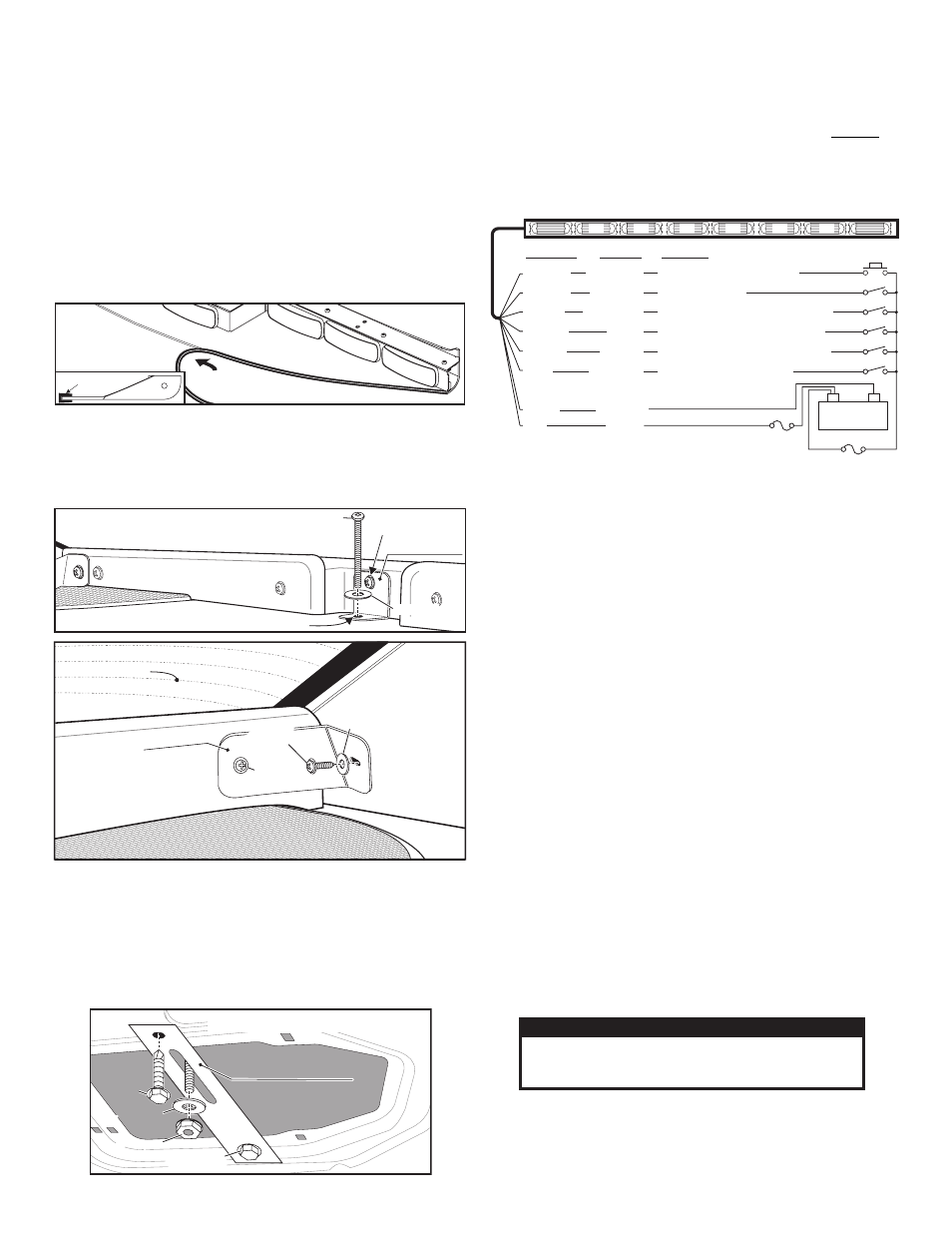
Fig. 4
Inside view of trunk
10 X 5/8" Hex
Head Screw
10-24 Elastic
Stop Nut
10-24 Elastic
Stop Nut
10-24 Elastic
Stop Nut
Rear Deck
Lightbar
Speaker
Speaker
Rear Windo
w
Window Defroster
Rear Window
Lightbar
Bolt goes through deck here
10-24 X 2-1/2 PPHMS
#10 Flat
Washer
Side Bracket
#10 Sheet
Metal Screw
Use
Existing
Screw
Use Existing Screw
#10 Flat Washer
Center Bracket
Fig. 2
Fig. 3
Speaker
Fig. 1
Side View / Seal Installation
Install seal on
leading edge of lightbar
SEAL
WHT/ORG
WHT/GRN
BROWN
WHT/BLK
ORANGE
BLUE
(WHT/BLK & ORG - Apply +12 volts simultaneously: Split T/A)
Scan-Lock™
End Flashers
T A
T A
T A Flash
Low Power
Left /
Right /
/
er
+12VDC
Ground (-)
See "Scan-Lock" Flash Patterns
See "Hi/Low Power"
Apply +12 volts: Activates End Flashers
Apply +12 volts: T/A sweeps to the Left
Apply +12 volts: T/A sweeps to the Right
Apply +12 volts: T/A lights flash
with the lightbar powered up
Wiring Diagram
All Fuses & Switches are Customer Supplied
10A Fuse
Wire Color
Function
Operation
3A Fuse
RED
BLACK
FLASHER
FLASHER
FLASHER
FLASHER
T/A
T/A
T/A
T/A
T/A
T/A
(+)
Battery
(-)