Important warning, Installation, Wiring – Whelen I02UFAAA User Manual
Page 2: Operation, Scan-lock™ / white, Hi/low power / green
Page 2
CAUTION! DO NOT LOOK DIRECTLY AT
THESE LEDS WHILE THEY ARE ON.
MOMENTARY BLINDNESS AND/OR EYE
DAMAGE COULD RESULT!
IMPORTANT WARNING!
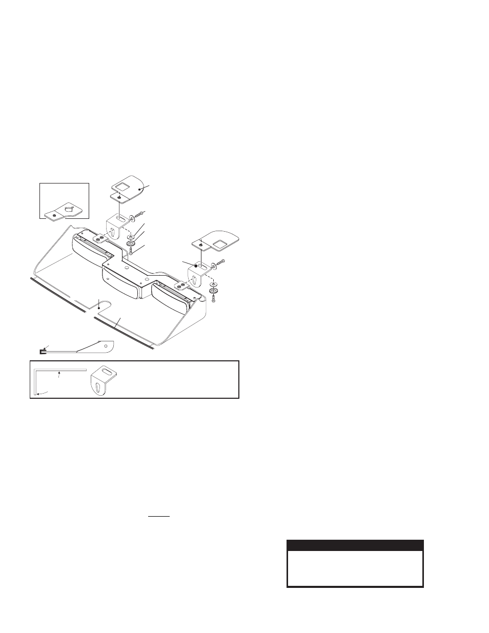
Depending on your vehicle’s roofline, it
may be necessary to bend the mounting
brackets to position the housing against
the windshield.
NOTE:
Bracket
Adjust angle
if necessary
Inboard Bracket
Qty. 2
Mounting Bracket:
2005½ - 06
Crown Victoria
Mounting Bracket:
2004 - 05
Crown Victoria
½
Black Oxide Screw
#10-32 X 3/8" / Qty 4
#10 External Tooth
Lock Washer / Qty 2
#10 Flat Washer / Qty. 4
Black Oxide Screw
#10-32 X 1/2" / Qty 4
Rear View Mirror here
Attach seal to front edge
SEAL
Side View / Seal Installation
IMPORTANT! Do not install this product or route any wires in the
deployment area of your air bag. See warning on page 1.
Installation:
IMPORTANT! The lightbar should be located a minimum of 16" from
any radio antennas!
When routing wires, it is important to choose a path that will keep the
wires away from excessive heat or any vehicle equipment that could
compromise the integrity of the wires (ex. trunk lids, door jams, etc.)
1.
Locate and install the rubber window seal onto the lower, leading
edge of the housing (see above).
2.
Remove the screws securing the visor clip to the vehicle, then
remove and retain the clip and all hardware.
3.
Locate the driver-side mounting bracket (indicated with a “D” label)
and orient as shown.
4.
Position the keyed opening of the mounting bracket directly under
the mounting location for the visor clip removed in step 1. With the
bracket in this position, remount the visor clip in its original location
using the original hardware.
5.
Repeat this procedure for the passenger-side mounting bracket
(indicated with a “P” label).
6.
Position the lightbar as shown below. Using the hardware provided,
secure the lightbar to the mounting brackets. Tighten hardware firmly.
7.
Route the lightbar cable down the vehicle A-pillar to the control head.
8.
Make all wiring connections using the information provided.
IMPORTANT: All customer supplied wires that connect to the
positive terminal of the battery must be sized to supply at least 125%
of the maximum operating current and FUSED at the battery to carry
that load. DO NOT USE A CIRCUIT BREAKER WITH THIS PRODUCT!
Wiring:
Refer to the parts pages for wiring diagrams of all lightbars.
WARNING: The strobe power supply is a high voltage device. Do not
remove flash tubes or dismantle the strobe light head assembly
while in operation. Wait 10 minutes after turning power off before
starting work or trouble-shooting.
Operation:
3 LINEAR-LEDs®: Powered and operated by a 4-conductor cable.
Turning lightbar on activates all lightheads. Choose flash pattern and
High or low power operation.
2 LINEAR-LEDs & 1 STROBE: Powered and operated by a 4-conductor
cable for the LEDs and a 3-conductor cable for the centr strobe light.
Turning lightbar on activates the two outer Linear-LEDs. To activate the
center strobe use a strobe power supply to power the 3-conductor cable.
2 MR8 TDs & 2 LINEAR-LEDs: Powered and operated by a 6-conductor
cable.
Turning lightbar on activates the two outer Linear-LEDs. Apply +12 volts
to the ORANGE wire to activate the MR8s.
2 MR8 TD's & 2 LINEAR-LEDs / CALIFORNIA STEADY: Lightbar is
powered and operated by a 6-conductor cable.
Turning lightbar on will activate the outer LEDs. The passenger side
LED will display the selected flash pattern and the driver side LED will
operate in steady burn mode. Apply +12 volts to ORANGE wire to activate
the MR8s.
Scan-Lock™ / WHITE
To change a flash pattern, turn on the desired lighthead:
TO CYCLE THROUGH ALL PATTERNS: To cycle forward apply +12
volts to the WHITE wire for less than 1 second and release. To cycle
backward apply +12 volts to the WHITE wire for more than 1 second and
release.
TO SET A PATTERN AS DEFAULT: When the desired pattern is
displayed allow it to run for more than 5 seconds.
TO RESET TO THE FACTORY DEFAULT PATTERN: Turn off power and
apply +12 volts to the WHITE wire while turning on power.
Note: A normally open momentary switch can be used to control
Scan-Lock operation.
Available Scan-Lock Flash Patterns:
SignalAlert™ 75 Alternating > SignalAlert™ 75 In-Out > SignalAlert™
75 Left to Right > SingleFlash 90 Alternating > SingleFlash 90 In-Out
SingleFlash 90 Left to Right > CometFlash® 75 Alternating >
CometFlash® 75, In-Out > CometFlash® 75, Left to Right > SingleFlash
75 Alternating SingleFlash 75 In-Out > SingleFlash 75 Left to Right >
SingleFlash 150 Alternating > SingleFlash 150 In-Out > SingleFlash
150 Left to Right DoubleFlash 75 Alternating > DoubleFlash 75 In-Out >
DoubleFlash 75 Left to Right > ActionFlash™ Alternating >
ActionFlash™ In-Out > ActionFlash™ Left to Right > RandomFlash >
ActionScan™ Alt. > ActionScan™ In-Out > ActionScan™ Left to Right.
Hi/Low Power / GREEN
This feature allows the user to step the unit down to low power
operation for nighttime use. The type of switch used depends on
how the operator wishes the Hi/Low feature to function:
Latching Mode: By applying positive voltage to the GREEN wire for less
than 1 second, the lightbar is “latched” into low power. The unit must be
turned off and then back on to restore normal high power operation (a
momentary switch is preferred).
Level Mode: Applying positive voltage to the GREEN wire for more than 1
second holds the lightbar in low power mode until voltage is removed (a
toggle switch is preferred).
IMPORTANT! Before returning this vehicle to active service, visually
confirm the proper operation of this product, as well as all vehicle
components/equipment.