Installation / full bar, Page 3 – Whelen I06UF4P User Manual
Page 3
Page 3
28
1 9
2 12
27
14
16
17
22
10
11
20
18
3
7
8
13
21
23 24
25 26
19
5
4
15
6
33 35
10
12
10
5 6 - 0 2 3 5 7 7 - 0 0 0
12
2 6 - 0 2 1 5 0 0 1 - 0 6
11 - 4 8 6 0 7 2 - 0 0 0
0 1 - 0 6 8 6 3 8 6 - 0 2
0 1 - 0 6 8 6 3 8 6 - 0 3
0 1 - 0 6 8 6 3 8 6 - _ 1
0 2 - 0 1 4 6 6 1 5 - 0 0
1 3 - 0 6 2 C 4 0 - 1 6 J
0 7 - 2 8 4 5 0 6 - 0 2 3
0 7 - 7 8 4 5 0 7 - 0 2 3
1 0 - 0 5 2 3 5 5 4 - _ _
3 8 - 0 5 4 3 2 0 8 - 0 4
0 7 - 2 4 3 3 6 0 - 0 2 3
1 5 - M 2 3 B 1 C - 1 2 0
0 2 - 0 1 8 6 3 7 3 - 0 0
4 0 - 0 6 2 0 4 0 0 - 0 3
1 4 - 0 4 0 2 1 6 - 1 2 0
6 8 - 1 9 0 0 3 7 5 - 3 0
0 2 - 0 3 2 3 5 4 7 - 0 0
0 2 - 0 1 8 6 3 7 9 - 0 0
1 5 - 0 6 5 2 1 B - 0 6 0
2 1 - 11 0 9 1 2 0 2 - 0
11 - 4 8 4 5 0 1 - 0 0 0
0 1 - 0 6 8 6 3 8 6 - _ 0
12
1
1
1
1
1
29
1
11
10
1
1
1
1
A/R A/R
1
1
1
1
1
1
29
1
1
1
29
1
1
29
10
1
11
11
11
12
18
12
24
1
20
10
1
1
18
4
1
1
1
2
10
20
1
1
1
24
12
18
1
1
1
1
1
18
1
1
1
4
4
1
1
1
4
1
1
1
2
2
1
2
0 2 - 0 1 6 C 2 9 6 - 3 0
0 2 - 0 1 6 C 2 9 6 - 2 0
0 2 - 0 1 6 B 7 5 3 - A 0
A/R
A/R
A/R
A/R
A/R
A/R
A/R A/R
A/R
A/R A/R
A/R
PCB 6 LED ARRAY - WHITE
PCB 6 LED ARRAY - BLUE
PCB 6 LED ARRAY - PCAMBER
0 1 - 0 2 6 B 0 6 8 - 3 4
0 1 - 0 2 6 B 0 6 8 - 3 3
2
3
ITEM
PART NUMBER
DESCRIPTION
QTY QTY QTY QTY
11
12
13
14
15
16
17
18
19
20
4
5
6
7
8
9
10
1
21
22
CO-THERM INSULATOR
PASS 3 LED T.D. FULL Inner Edge®
DRVR 3 LED T.D. FULL Inner Edge®
FULL SEE-THRU
10-LT 2 T-D
Inner Edge®
FULL SEE-THRU
12-LT 2 T-D
Inner Edge®
FULL
10-LT 2 T-D
Lo-Pro™ Inner Edge®
FULL Lo-Pro™ Inner Edge® 12-LT 2 T-D
REFLECTOR/COLLIMATOR LINEAR
DRIVER SIDE (2) WAY MIRROR BUCK
BRACKET LIGHTHEAD MOUNT
PLATE, MOUNTING
SCREW, 6 X 3/8 PPH PLASTI-LOK
SCREW GROMMET, #6/8
HOUSING, FRONT FULL 2006 CROWN VIC
GROMMET, 3/8
1 LIGHT CONNECTOR BOARD, SMT
BRACKET, MOUNTING
SCREW, M4.2 X 12mm PHIL WSHRHD BLK
ASS'Y, PCB CONNECTOR
HEADER, .1" X 2 POS DOUBLE
SCREW, 4 X 3/4 PPHMS SS
ASSY, PCB MOTHER/CONTROL BOARD
TY WRAP, 6"
LABEL
SEAL, EXTRUDED
LIGHT PIPE
24
25
23
0 1 - 0 4 8 6 3 8 6 - 2 0
11 - 4 8 6 7 2 5 - 0 0 0
0 1 - 0 4 8 6 3 8 6 - 1 0
11 - 4 8 6 7 0 9 - 0 0 0
4 6 - 0 7 6 B 8 2 0 - 0 0
3 9 - 1 M 1 7 6 7 2 - 0 8
4 6 - 0 7 4 6 6 1 6 - 0 0
0 1 - 0 4 8 4 6 4 3 - 0 0
0 2 - 0 1 6 C 2 9 6 - 5 0
0 2 - 0 1 6 C 2 9 6 - 4 0
4 6 - 0 7 4 3 4 0 3 - 0 0
A/R
A/R
A/R
A/R
1
1
2
1
1
A/R
A/R A/R
A/R
1
1
1
1
2
2
1
1
2
A/R
A/R
1
1
1
A/R
1
A/R
A/R A/R
A/R
A/R
A/R
A/R
HSNG, FRONT FULL 2011 EXPEDITION
HARNESS, INTERCONNECT
HOUSING, PLUG 8 POS
HARNESS, TAKE-DOWN
PCB 6 LED ARRAY - RED
PCB 6 LED ARRAY - GREEN
ASSY, CABLE INPUT 18 GA 20'
HOUSING, FRONT FULL 2011 TAHOE
KIT, MOUNTING 12 LT 2011 TAHOE
KIT, MTG 12 LT 2011 EXPEDITION
26
27
28
29
30
31
32
KIT, MOUNTING 12 LT 2006 CROWN VIC
33
34
35
36
CONFIGURATION
0 =
1 =
2 =
3 =
12-LT W/2 T-D
10-LT W/ 2 T-D
12-LT W/2 T-D-SEE THRU BUCK
10-LT W/2 T-D-SEE THRU BUCK
MODEL
0 =
1 =
2 =
CROWN VICTORIA
EXPEDITION
TAHOE
0 1 - 0 6 8 6 3 8 6 - _ _
PART NUMBER KEY
Position
Inboard
Outboard
-
-
Vehicle
All except
Lo-Pro
Tahoe
Crown Vic
Impala
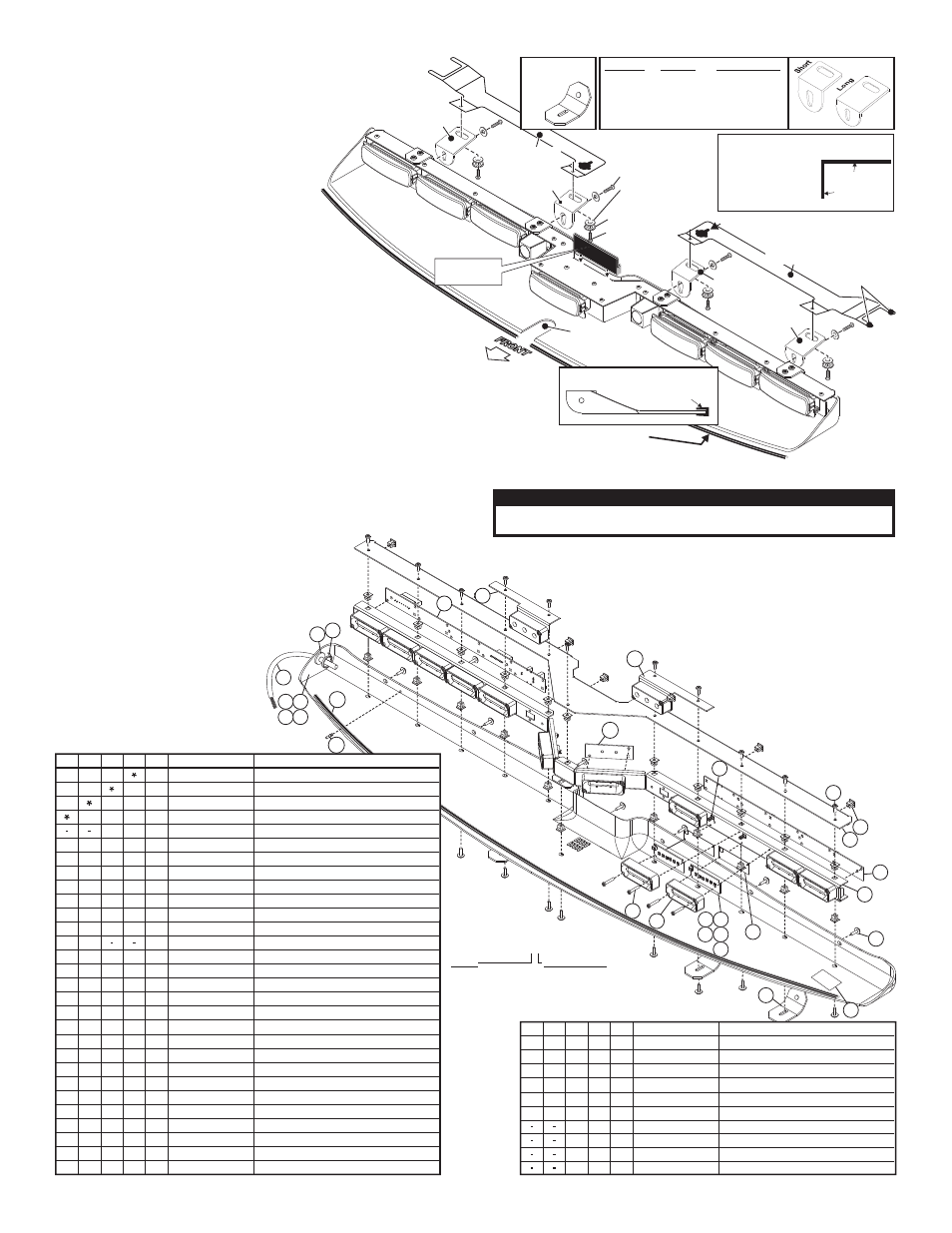
Bracket Used
Short Bracket
Short Bracket
Long Bracket
Long Bracket
Depending on the vehicle’s roofline, it
may be necessary
to bend the mounting
brackets to position
the housing against
the windshield.
NOTE:
Inboard
Bracket
Inboard Bracket
Outboard Bracket
Outboard Bracket
Mounting
Fingers
Keyed Opening
Relief for rear
view mirror
stem
Windshield Seal
SEAL
Side View / Seal Installation
Black Oxide Screw
#10-32 X 3/8" Qty 4
Black Oxide Screw
#10-32 X 1/2" / Qty 4
#10 .631 X .060
Flat Washer / Qty. 4
#10 External Tooth
Lock Washer / Qty. 4
Driver-Side
Mounting Bracket
Labeled "D"
06 Crown Vic
only
Lo-Pro
Passenger-Side
Mounting Bracket
Labeled "P"
Optical Gasket
2005 Impala
Adjust bracket
angle if
necessary
IMPORTANT! Do not install product or route any wires in the
deployment area of your air bag. (See air bag warning Pg. 1).
IMPORTANT! The lightbar should be located a minimum
of 16" from any radio antennas!
Important note for Chevrolet Impalas:
When mounting to a Chevrolet Impala, the optical
gasket must be installed. Failure to do so could
result in reflected light within the passenger
compartment.
Installation / Full Bar:
When routing the wires, it is important to choose a
path that will keep the wires away from excessive heat
or any vehicle equipment that could compromise the
integrity of the wires.
1.
Locate and install the rubber window seal onto the lower, leading
edge of the housing.
2.
Using an appropriately sized Torx® head screwdriver, loosen the three
screws securing the driver-side visor swivel bracket to the vehicle. Do
not remove these screws.
3.
Remove the screws securing the visor clip to the vehicle. Remove and
retain the clip and all hardware.
4.
Locate the driver-side mounting bracket (indicated with a “D” label).
Orient bracket as shown.
5.
Slide the mounting bracket fingers between the loosened swivel bracket
and the headliner. The bracket fingers should straddle the inner section
of the swivel bracket when properly oriented.
6.
Position the keyed opening of the mounting bracket directly under the
mounting location for the visor clip removed in
step 2. With the bracket in this position, re-
mount the visor clip in its original location using
the original hardware. Firmly tighten any hardware
loosened in this procedure.
7.
Repeat this procedure for passenger-side
(indicated with a “P” label).
8.
Using provided #10-32 x 3/8” black oxide screws, secure the
lightbar to the mounting brackets. Tighten this hardware
firmly. Route lightbar cable down vehicle A-pillar to
control head. See previous page for wiring.
CAUTION! DO NOT LOOK DIRECTLY AT THESE LED’S WHILE THEY ARE ON.
MOMENTARY BLINDNESS AND/OR EYE DAMAGE COULD RESULT!
I M P O R TA N T W A R N I N G !
- I06UF5P I06UF8 I06UFZ I13UF4P I13UF5P I13UF8 I13UFZ I08UF4P I08UF5P I08UF8 I08UFZ I39UF4P I39UF5P I39UF8 I39UFZ I41UF4P I41UF5P I41UF8 I41UFZ IZ06UF4P IZ06UF5P IZ06UFZ IZ13UF4P IZ13UF5P IZ13UF8 IZ13UFZ IZ30UFZ IZ30UFX IZ36UF4P IZ36UF5P IZ36UF8 IZ36UFZ IZ08UF4P IZ08UF5P IZ08UF8 IZ08UFZ IZ34UFZ IZ41UF4P IZ41UF5P IZ41UF8 IZ41UFZ IZ39UF4P IZ39UF5P IZ39UF8 IZ39UFZ IZ33UF4P IZ33UF5P IZ33UF8 IZ33UFZ IZ19UF4P IZ19UF5P IZ19UF8 IZ19UFZ IZ31UFZ IZ31UFX IM06UF8 IM06UFZ IM13UF8 IM13UFZ IM10UFZ IM38UF8 IM38UFZ