Whelen IZ38LR8 User Manual
Page 2
Page 2
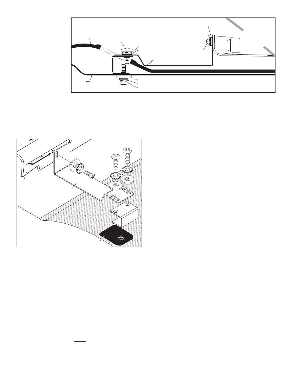
Use second hole in,
from outer edge of lightbar
CHILD RESTRAINT TETHER
ADJUSTABLE BUCK
MOUNT BRACKET
LIGHTBAR
HOUSING
DECK
MOUNT
BRACKET
DECK
MOUNT
BRACKET
DECK
MOUNT
BRACKET
REAR
DECK
REAR
DECK
REAR
DECK
Installation:
IMPORTANT! The lightbar
should be located a
minimum of 16” from any
radio antennas!
1.
On the rear deck
(passenger side) locate
the cap covering the child
restraint strap holder.
Snap the cover open to
access the bolt, then
remove the bolt and lift off
the cap.
2.
Locate the passenger side
adjustable buck mount
bracket and a deck mount
bracket included with the mounting kit. Secure the deck mount bracket
onto the strap holder using the 1/4 - 20 X 3/4 inch Hex Head Machine
Screw, 1/4 inch External Tooth Lock Washer and 1/4 inch Flat Washer
provided. and tighten hardware firmly.
3.
Next, loosely secure the adjustable buck mount bracket to the deck mount
bracket using the supplied 1/4 - 20 X 5/8 inch Phillips Pan Head Machine
Screws, 1/4 inch External Tooth Lock Washers and 1/4 inch Flat Washer.
4.
Repeat steps 1 - 3 for the Driver-side mounting bracket.
5.
Position the lightbar onto the rear deck and secure the lightbar to the two
buck mount brackets using the hardware shown.
6.
Hold the lightbar housing firmly against the glass as you tighten the
hardware securing the buck mount brackets to the deck mount brackets.
Make sure that the rubber window seal on the lightbar housing fully
engages the rear window. The lightbar should maintain the seal against
the windshield when the pressure is released.
7.
Route the input cable to your control head (refer to the installation manual
included with your control head for wiring information).
IMPORTANT! When routing the lightbar cable, it is left to the installation
technician's discretion to select a path for these cables that will both protect the
cables from possible damage and not interfere with the operation of any other
vehicle components or equipment. Refer to the instructions included with your
switches for switch wiring information.
Wiring and Operation:
WARNING! All customer supplied wires that connect to the positive
terminal of the battery must be sized to supply at least 125% of the
maximum operating current and FUSED at the battery to carry that load.
DO NOT USE CIRCUIT BREAKERS WITH THIS PRODUCT!
BLACK - Ground
Extend and connect the BLK wire to the ground terminal of the vehicle battery.
RED - Main Power
Route the RED wire to an unused, ignition-controlled circuit fused @ 10 Amps.
Do not connect to this circuit yet.
When this product is wired as outlined here, the lightbar will not
function until the ignition switch is in the ON, RUN or ACC position.
WHT-ORG - Scan-Lock™ Flash patterns
When the TA feature is active, this wire will select TA patterns; when the
end flasher feature is active, this wire will select the end flasher patterns.
Do not use Scan-Lock™ while both features are simultaneously active.
TO CYCLE THROUGH ALL PATTERNS: Apply +12 volts to the WHT/
ORG wire for less than 1 second and release. To cycle backward apply
+12 volts for more than 1 second and release.
TO SET A PATTERN AS DEFAULT: When the desired pattern is
displayed, allow it to run for more than 5 seconds. The lightbar will now
display this pattern when active.
TO RESET TO THE FACTORY DEFAULT PATTERN: Turn off power,
apply +12 volts to the WHT/ORG wire, then turn power on.
A Normally Open Momentary Switch is best for this circuit. Fuse @1A.
WHT/GRN - Low Power Operation
For low power operation apply +12VDC to the WHT/GRN wire. The unit
will continue to operate in Low Power mode until this voltage is removed.
A SP/ST switch is best suited for this circuit. Fuse this wire @1A.
BROWN - End Flashers
Applying +12VDC to this wire activates the end flashers. A SP/ST switch
is best suited for this circuit. Fuse this wire @1A.
BLUE - TA Flash
When +12VDC is applied to this wire, the Traffic Advisor™ lightbar
function becomes active. A SP/ST switch is best suited for this circuit.
Fuse this wire @1A.
ORANGE - Left
When +12VDC is applied to this wire, the lights sweep from right to left. An
SP/ST switch is best suited for this circuit. Fuse this wire @1A.
WHT/BLK - Right
When +12VDC is applied to this wire, the lights sweep from left to right. An
SP/ST switch is best suited for this circuit. Fuse this wire @1A.
NOTE: If you apply power to both the WHT/BLK and ORG wires
simultaneously, you will get a split pattern. Both sides will start at the
center and sweep outward.
IMPORTANT! Before returning the vehicle to active service, visually
confirm the proper operation of this product, as well as all vehicle
components/equipment.
1. SignalAlert™
2. CometFlash®
Scan-Lock End Flasher Patterns:
3. SingleFlash 375
4. SingleFlash 75
1. Seq. to Solid 2. Seq. On/Seq. Off
Traffic Advisor Patterns:
3. 1-Lamp TripleFlash™ 4. 2-Lamp TripleFlash
5.
6.
ActionFlash™
ActionScan™
INSIDE
TRUNK
REAR
DECK
R E A R
D E C K
MOUNT
LIGHTBAR
ADJUSTABLE
BUCK MOUNT
#10 FLAT WASHER
10 - 32 X ½ INCH
PHILLIPS PAN HD
METAL SCREW
1/4 - 20 X 5/8 INCH
PHILLIPS PAN HD
MACHINE SCREW
1/4 - 20 X 3/4 INCH HEX HD MACHINE SCREW
#10 EXTERNAL TOOTH
LOCK WASHER
1/4” FLAT WASHER
1/4” FLAT WASHER
1/4 INCH EXTERNAL TOOTH LOCK WASHER
1/4 INCH EXTERNAL
TOOTH LOCK WASHER
REAR WINDOW