Installation, Operation, Page 2 – Whelen RP13AA User Manual
Page 2
Page 2
Wire Color
Function
White/Violet
Scan-Lock™
Grey (Connects to other Sync wires)
SYNC
Black (12V) or Black/White (24V)
To Ground
LED Color
Red/Wht (two-color split models)
Wht/Red (single-color split models)
or
or
Split Lighthead Operation:
PHASE 1
LEFT
RIGHT
side lights up and
with
side.
alternates
PHASE 2
RIGHT
LEFT
side lights up and
with
side.
alternates
PHASE 3
BOTH sides flash together
(ON-OFF-ON).
PHASE 4
BOTH sides flash together
(OFF-ON-OFF).
Phases 3 & 4 are visually indistinguishable.
ON
ON
OFF
OFF
ON
OFF
ON
OFF
ON
ON
OFF
OFF
ON
ON
OFF
OFF
ON
ON
OFF
OFF
ON
ON
OFF
ON
ON
OFF
47. ModuFlash™
48. ModuFlash™
64. ActionScan™
49. DoubleFlash 120
50. DoubleFlash 120
51. PingPong™ 120
52. PingPong 120
53. TripleFlash™ 75
54. TripleFlash 75
55. TripleFlash 120
56. TripleFlash 120
57. SigAlert Cal.™
58. SigAlert Cal.
59. Action SF 60/120
60. Action SF 60/120
61. Action SF60/TF120
62. Action SF60/TF120
63. CalScan™
65. SteadyFlash 60
66. SteadyFlash 75
67. SteadyFlash 90
68. SteadyFlash 120
69. Steady & Steady
LINZ6™
SingleFlash 120
SingleFlash 300
DoubleFlash 150
ComAlert 150
ActionFlash™1
ActionFlash 2
ModuFlash™
.ActionScan™
Steady
17.
18.
19.
20.
21.
22.
23.
24
25.
Phase 1 flashes
with Phase 1
simultaneously
Phase 2 flashes
with
2
1
with
2
simultaneously
alternates
Phase
Phase
Phase
Phase Operation
Lamp Driver
RED
BLK
GRN
WHT
- Power
- Ground
- SYNC
- Scan-Lock
(FUSE @ 3A)
(Connect to other Sync wires)
(FUSE @ 1A)
VERTEX™
Flash Patterns:
BOLD
NOTE:
= California Title XIII Compliant Pattern
= SYNC Pattern
Italic
1.SignalAlert™75
2.SignalAlert75
3.SignalAlert75
4.SignalAlert75
5.CometFlash®75
6.CometFlash75
7.CometFlash75
8.CometFlash75
17.ComAlert™75
18.ComAlert75
19.ComAlert75
20.ComAlert75
21.LongBurst™75
22.LongBurst75
23.LongBurst75
9.DoubleFlash75
10.DoubleFlash75
11.DoubleFlash75
12.DoubleFlash75
13.SingleFlash75
14.SingleFlash75
15.SingleFlash75
16.SingleFlash75
Phase 1
P
2
P
3
P
4
P
1
P
2
P
3
P
4
Phase 1
P
2
P
3
P
4
P
1
P
2
P
3
P
1
P
2
P
3
P
4
P
1
P
2
P
3
P
4
hase
hase
hase
hase
hase
hase
hase
hase
hase
hase
hase
hase
hase
hase
hase
hase
hase
hase
hase
hase
hase
ALT
SIM
ALT/SIM
ALT
SIM
ALT
SIM
ALT
SIM
ALT
SIM
ALT
SIM
ALT
SIM
ALT
SIM
ALT/SIM
24.LongBurst75
29.SSNF75
30.SSNF75
25.PingPong™75
26.PingPong75
27.PingPong75
28.PingPong75
31.SingleFlash 60
32.SingleFlash 60
SingleFlash
SingleFlash 0
35.SingleFlash 120
36.SingleFlash 120
SingleFlash 300
38.SingleFlash 300
DoubleFlash 150
40.DoubleFlash 150
41.ComAlert™ 150
42.ComAlert™ 150
43.ActionFlash™ 50
44.ActionFlash™ 50
45.ActionFlash™ 150
46.ActionFlash™ 150
33.
90
34.
9
37.
39.
P
4
P
1
P
2
P
1
P
2
P
3
P
4
ALT
SIM
ALT
SIM
ALT
SIM
ALT
SIM
ALT
SIM
ALT
SIM
ALT
SIM
ALT
SIM
hase
hase
hase
hase
hase
hase
hase
1. SignalAlert™75
2.
3.
4.
5.
6.
7.
8.
SignalAlert 75
CometFlash®75
CometFlash 75
DoubleFlash 75
DoubleFlash 75
SingleFlash 75
SingleFlash 75
SYNC Patterns
P
1
hase
2
1
2
1
2
1
2
Phase
Phase
Phase
Phase
Phase
Phase
Phase
ComAlert™
ComAlert
LongBurst™
LongBurst
PingPong™
PingPong
9.
10.
11.
12.
13.
14.
15.
16.
SingleFlash 60
SingleFlash 90
Non-SYNC Patterns
1
2
1
2
1
2
Phase
Phase
Phase
Phase
Phase
Phase
To +VBAT
(Fuse@3amps)
IMPORTANT! The lightbar should be a minimum of 16" from radio antennas!
Installation:
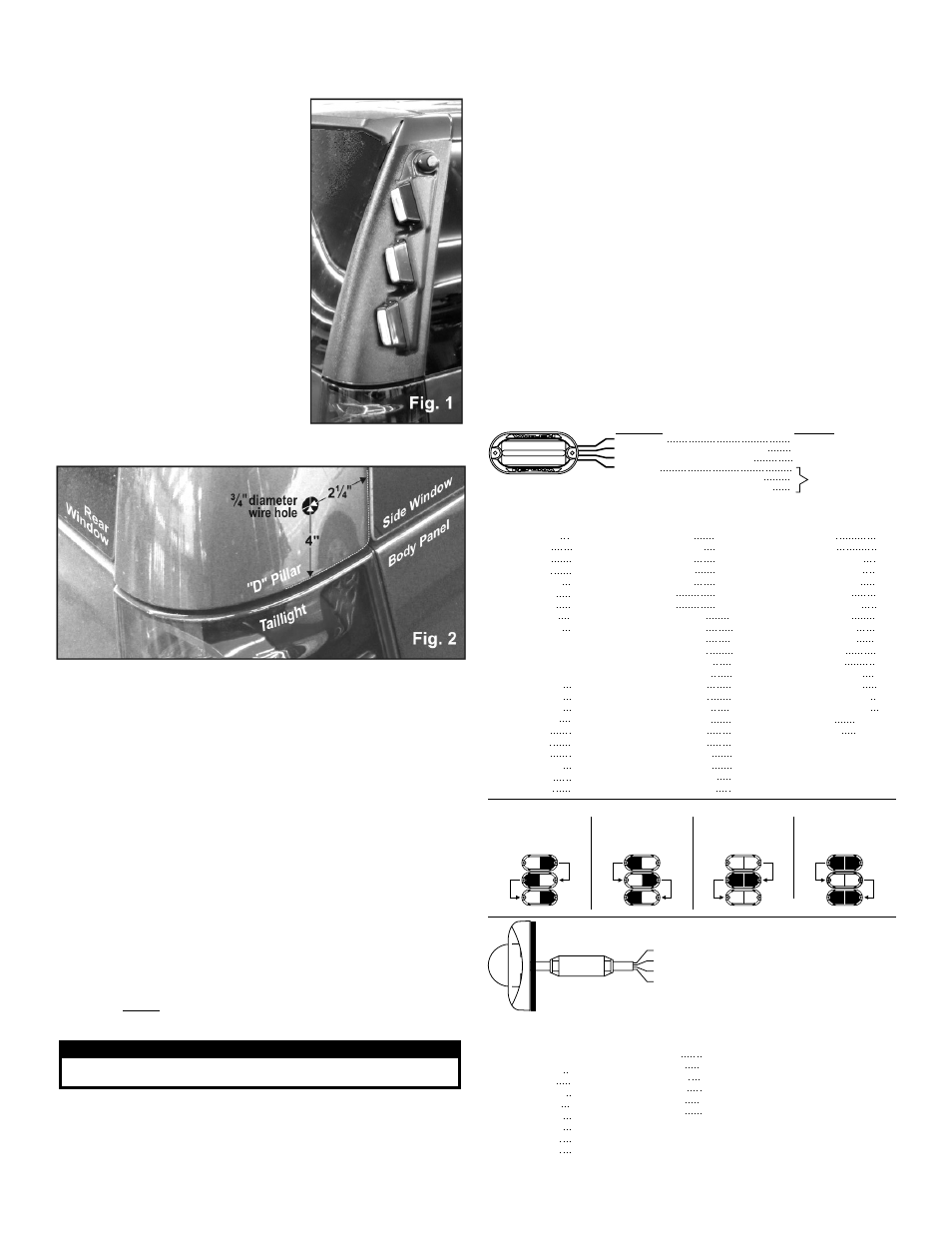
1.
First, place the lightbar onto the mounting
location. The trimmed edge of the lightbar
should be flush with the bottom edge and
each outer edge of the "D" Pillar (Fig. 1).
2.
Mark off and drill a 3/4” wire entry hole into
the "D" pillar using the measurements shown
(Fig. 2). Be very careful not to damage any
components behind the “D” Pillar.
Measure 2-1/4” from the leading edge and 4”
from the bottom edge of the “D” Pillar. The
wire entry hole will be located beneath the
bottom pod of the lightbar.
3.
Remove the 2 screws holding on the taillight
(which overlaps the “D” Pillar) and pull the
taillight out.
4.
Install the wiring and make all the wiring
connections (See wiring diagrams) then
reinstall the taillight.
Mounting the housings:
1.
Place the lightbar onto its mounting location
on the vehicle to be sure the lightheads have
a sufficient service loop for lighthead
replacement or service. Once mounted, the
housing is not easily removed.
2.
Using isopropyl alcohol (70%), clean the vehicle where it will come in contact
with the mounting tape then prime those areas with the supplied 3M Keel
Primer. Ready the leaders on the pre applied tape. Be sure the leaders are
protruding from under the housing so that you can pull the tape backing off
once the housing is in place.
3.
There is a driver and passenger side housing. Be sure to mount them on
the correct sides. Firmly hold the lightbar onto its final mounting position.
While pressing the whole housing against the “D” Pillar, (being very careful not
to move the housing) slowly remove the tape backing from the top and leading
edge of the housing and then from the rear.
4.
With the tape backing removed, press the housing firmly against the mounting
surface where the tape is, to secure it.
WARNING! The adhesive used in this procedure is fully bonded after 72
hours @ 70°F (21°C). During this period, do not expose the lights to any
unnecessary force, such as a high-pressure car wash.
IMPORTANT! It is the responsibility of the installation technician to make sure
that the installation and operation of this product will not interfere with or
compromise the operation or efficiency of any vehicle equipment!
WARNING! All customer supplied wires that connect to the positive terminal
of the battery must be sized to supply at least 125% of the maximum operating
current and FUSED at the battery to carry that load. DO NOT USE CIRCUIT
BREAKERS WITH THIS PRODUCT
Operation:
Scan-Lock™
This feature allows you to program a selected flash pattern into a lighthead. The
lighthead must be activated to use Scanlock. The Scanlock™ wire is WHITE/VIOLET
on the LINZ6™ and WHITE on the Vertex™.
To cycle forward through patterns apply power to the Scanlock wire for less than 1
second and release.
To cycle backward through patterns apply power to the Scanlock wire for over 1
second and release. When the desired pattern is displayed, allow it to run for more
than 5 seconds. The lighthead will now display this pattern when active.
To reset to the factory default pattern Turn off power. Apply power to the Scanlock
wire while turning power back on.
Sync
The SYNC wire is GREY on the LINZ6™ and GREEN on the Vertex™. For SYNC to
operate, you must connect the SYNC wires together. If you do not want to use the
sync feature, cap the sync wires.
To sync two lightheads, configure both lightheads to display the same Phase 1
pattern. With the power off, connect the SYNC wires from each lighthead
together. When the lightheads are activated, their patterns will be
synchronized. To configure lightheads to alternate their patterns, advance the
pattern of that lighthead to the Phase 2 mode of the current pattern. The same
concept applies to Phases 3 & 4.
CAUTION! DO NOT LOOK DIRECTLY AT THESE LED’S WHILE THEY ARE ON.
MOMENTARY BLINDNESS AND/OR EYE DAMAGE COULD RESULT!
I M P O R TA N T W A R N I N G !