Fig. 1 fig. 2 fig. 3, Fig. 4, Installation – Whelen OE13UR8 User Manual
Page 2: Operation
Page 2
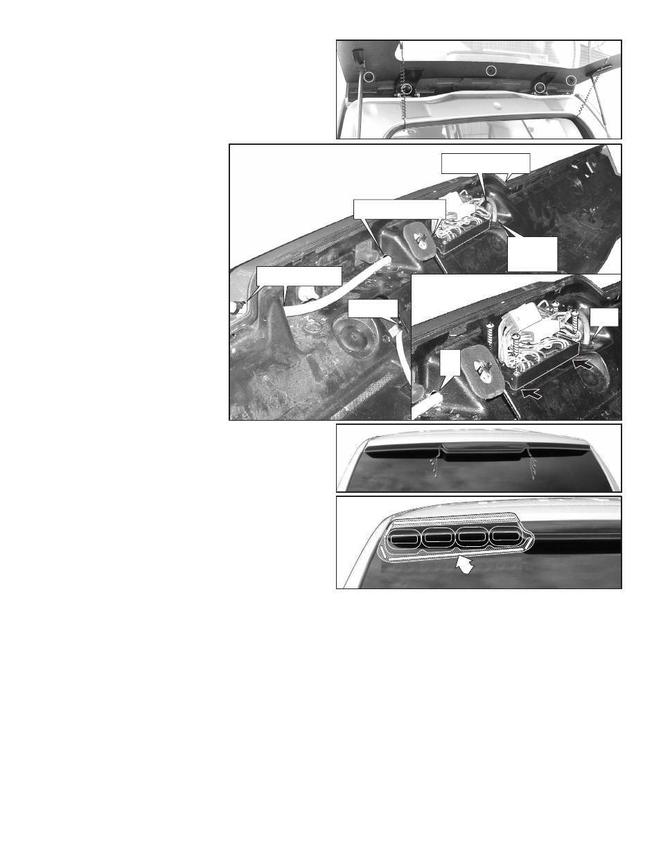
Fig. 1
Fig. 2
Fig. 3
FLASHER
Prime the areas where the mounting
tape will contact the window
Fig. 4
BRAKE LIGHT
Mount flasher
as far in as
possible
Mount flasher
as far in as
possible
Mount flasher
as far in as
possible
Drill two 7/16" holes and
feed light cable through
Drill two 7/16" holes and
feed light cable through
Drill two 7/16" holes and
feed light cable through
Drill 7/16"
h o l e a n d
feed control
cable through
Control Cable
e x i t s h e r e
Control
C a b l e
7/16"
Wire
Hole
IMPORTANT! The lightbar should be a minimum of 16" from any radio antennas!
Installation:
Preparing the spoiler:
1.
Remove the rear spoiler from the vehicle. 5 bolts hold the spoiler on (Fig. 1).
2.
Drill two 7/16” wire holes on each side of the spoilers brake light (Fig. 2) and two
holes opposite these holes on the inside of the spoiler housing and run both wire
harnesses through as shown in Figure 2.
3.
Drill two more 7/16” holes (Fig. 2) in the center of the spoiler to run the passenger
side lighthead harness through to the flasher.
4.
There is a circular mark on the spoiler for a cable
cut-out. Use this mark to locate the control cable
hole (Fig. 2). Drill a 7/16” control cable hole into
the spoiler.
5.
Mount the flasher to the spoiler as shown (Fig. 2).
Mount the flasher as far in from the edge as
possible to keep it from hitting the rear window.
6.
Feed the 2 lightbar harness cables into the holes
you drilled near the brake light and up to the
flasher. Also feed the control cable into the hole
you drilled and run it out through the existing hole
as shown in Figure 2. NOTE: You must install
the lightbar harness cables onto the correct
sides of the lightbar. The “driver side” cable
will be the longer of the two cables. Also, be
sure the connectors coming from the flasher
plug into the correct harness.
7.
Attach the Deutsch connectors to the lighthead
wiring harness and control cable as shown in the
wiring diagram. Plug the cables into the flasher
and dress connectors approximately as shown.
8.
Drill a 7/16” hole into the vehicle next to the
existing vehicle brake light cable hole.
9.
Run the control cable out through the hole you
drilled in step 8 and remount the spoiler (Fig. 3).
10.
Connect to power to check the lightheads for
proper operation.
Mounting the housings:
1.
Hold the housing onto the mounting surface in its exact mounting location and
trace the top and bottom outline onto the vehicle with a grease pencil (Fig. 4).
IMPORTANT: There is a driver and passenger side housing. Be sure to
mount them on the correct side. The passenger side housing has a cut-out
on the bottom to allow the rear wiper to clear the housing.
2.
Using the isopropyl alcohol (70%), clean the vehicle where it will come in contact
with the mounting tape. Within the outlines you traced, prime the areas that come
in contact the mounting tape with the supplied 3M Keel Primer (Fig. 4).
3.
Plug the lighthead cable into the lightheads following the wiring diagram.
4.
Place the housing back in its exact mounting position. The backing on the
mounting tape has leaders. Be sure the leaders are protruding from under the
housing so that you can pull them off once the housing is in place.
5.
Hold the housing firmly in place in the exact mounting location while you pull the
backing off of the tape being very careful not to move the housing.
6.
With the backing removed, press the housing firmly against the mounting surface
where tape is, to secure it. WARNING! The adhesive used in this procedure is
fully bonded after 72 hours @ 70°F (21°C). During this period, do not expose the lights to any unnecessary force, such as a high-pressure car wash.
7.
Extend the control cable to your power source and follow the wiring diagram.
Operation
:
WHITE (Scan-Lock™)
Activate the RED wire to turn on the lightbar (lightbar will be flashing) and choose a
pattern. Or you may activate the function you wish to change and choose a pattern.
To cycle forward through patterns apply power to the WHT wire for less than 1
second and release.
To cycle backward through patterns apply power to the WHT wire for over 1
second and release. When the desired pattern is displayed, allow it to run for more
than 5 seconds. The lighthead will now display this pattern when active.
To reset to the factory default pattern Turn off power. Apply power to the WHT wire
while turning power back on.
Function Wires:
RED (model OE13UR8) (Flashers): Apply power to the RED wire activates all
lightheads in flash mode.
RED (model OE13UR8T) (Power): Connects to the positive terminal of the battery
and provides power to the lightbar.
ORANGE (model OE13UR8) (Low Power): Apply voltage to the ORANGE wire to
make the lightbar step down to low power and remove voltage for normal operation.
ORANGE (model OE13UR8T) (End Flashers) Apply power to the orange wire
engages the end flashers.
BLUE (Sequence to Left): With the unit activated, applying +12V DC to the BLUE
wire causes lightheads to flash, starting at RIGHT and flashing toward LEFT.
GREEN (Sequence to Right): With the unit activated, applying +12V DC to the
GREEN wire causes lightheads to flash, starting at LEFT and flashing toward RIGHT.
BLUE and GREEN (Split T/A): Activating both the GREEN and BLUE wires at the
same time will give you a split TA pattern.
Caution: Permanent mounting of this product will require drilling. It is
absolutely necessary to make sure that no other vehicle components could be
damaged by this process. Check both sides of the mounting surface before
starting. If damage is likely, select a different mounting location.
IMPORTANT! Before returning the vehicle to active service, visually confirm
the proper operation of this product, as well as all vehicle components/
equipment.