Fig. 1 corner strobe / top view of lightbar base, Corner strobe / end view of lightbar base fig. 2, Endcap, alley light and gasket – Whelen 9MSCANLK User Manual
Page 2: Scan-lock™: installation, Removing the endcap and lenses
Page 2
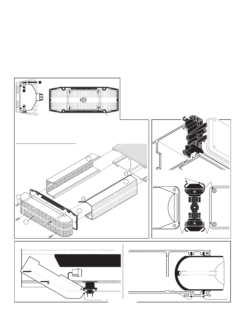
Edge of lighthead snaps into clips on bracket.
Lighthead or Panel mounting
holes snap into the raised
bosses on mounting bracket.
Ears on mounting bracket slide into
the channels in the lightbar base.
CORNER
STROBE
LIGHTHEAD
or
FILLER
PANEL
Fig. 1 Corner Strobe / Top view of lightbar base
Tabs slide
into base
END VIEW OF
LIGHTBAR BASE
Slide spacer
into bar
REAR OF LIGHTBAR
(Drivers Side)
CENTER WALL of LIGHTBAR BASE
CORNER
STROBE
POWER SUPPLY
TAB
Lighthead snaps into
mounting bracket here.
If you are installing a new
strobe lighthead, snap this
bead off of the bottom of
the new reflector
Corner Strobe / End view of lightbar base
Fig. 2
Remove the screws (A) that hold the endcap
on and pull the endcap and gasket (C) off.
4
(B)
Slide lenses
(D) out of the lightbar, to gain access to the extrusion. When reinstalling the lenses and spacers, install the
cord seal (NFPA / See below). When reinstalling the endcap, place the endcap gasket into its position on
the endcap and line up all the tabs and holes. Spacers (not shown) mount the same as lenses.
Removing the Endcap and Lenses
D
D
C
Insert
cord
seal
into
track
in
lens
A
B
Seal Cord Installation / NFPA MODELS ONLY:
Cut the seal cord approx. 1-1/2" longer than the extrusion on each side.
Rub silicone over the cord seal leaving 3 to 4 inches on one end dry.
Beginning with 1 corner lens, start the lens into the bottom
lens track. Place the cord seal onto the groove in the
top of the lens eav 1 to 2 inches
Hold onto the left end of the seal hanging
out and slide the corner lens into
position.
1 -
2 -
3 -
4 -
3 -
3 -
4 -
4 -
. L
e
free.
Inspect the seal cord for any areas that have
wrinkled. Especially around the dividers.
Push lenses together tight and trim excess
seal cord at each end.
6 -
7 -
6 -
7 -
From the opposite end of the
lightbar, pull the seal
cord tight and install
the remaining lenses
and divider.
5 -
5 -
5 -
5 -
5 -
NOTE: Lens dividers must be
installed as each lens is put
into position
Endcap, Alley Light and Gasket
Place endcap gasket onto endcap locating all tabs and holes
1
A l i g n
Lighthead
with the 4
bosses in
the endcap
Snap Lighthead
into 4 barbs in
endcap
2
Lighthead
Gasket
Scan-Lock™: Installation
The Scan-Lock™ harness will plug into the power distribution board
located on the center inner wall of the lightbar base. The cable will exit
the lightbar along with the main cable. Always cut power before
starting installation.
WARNING: The strobe light power supply is a high voltage device.
Do not remove the strobe tubes or dismantle the strobe lightheads
in the system while the unit is in operation. Wait 10 minutes after
turning off power Before starting any work on the system.
1.
Remove the endcaps. If your lightbar is equipped with alley lights
you must unplug them before fully removing the endcap.
2.
Remove any lenses, lightheads or filler panels necessary (Figs. 1
& 2) to reach the power distribution board.
3.
Wire the Scan-Lock™ cable in as shown in the wiring diagram
then tie-wrap the Scan-Lock cable to the main cable following the
main cable out of the lightbar.
4.
Reinstall any lightheads into the lightbar base along with any
existing options you removed. To reinstall the lightheads and
lenses in proper order, you may refer to the switch operations
sheet that comes with the lightbar.
5.
Plug in the alley lights (if present) and replace the endcaps.
Installation is now complete and you may test the Scan-Lock
option by following the instructions on the wiring diagram.
IMPORTANT: It is the responsibility of the installation technician
to make sure that the installation and operation of this product
will not interfere with or compromise the operation or efficiency
of any vehicle equipment.
IMPORTANT! Before returning this vehicle to active service,
visually confirm the proper operation of this product, as well as
all vehicle components/equipment!