Whelen FC4JJJJ User Manual
Page 4
Page 4
IMPORTANT! It is the responsibility of the installation technician
to make sure that the installation and operation of this product will
not interfere with or compromise the operation or efficiency of any
vehicle equipment!
Routing your Lightbar Cable(s):
1.
To protect the headliner from damage caused by drilling the cable access
hole through the vehicle roof, allow a 5” to 7” distance between roof and
headliner by lowering the headliner before drilling.
2.
Using a 1” hole saw, drill the cable access hole.
NOTE: There may be a roof support member that spans the distance between the driver’s and passenger’s side. DO NOT DRILL THROUGH
THIS MEMBER! Adjust the location until the hole can be drilled without contacting this support member.
3.
Use a round file to smooth and de-burr the edges of the hole.
4.
Install a 1” grommet (user supplied) into the cable access hole.
5.
Insert the cable(s) through the cable access hole into the vehicle. Use RTV silicone to weatherproof the access hole after the cable(s) are pulled
completely into the vehicle.
Route the cable(s) one at a time to their respective destinations (power cable to vehicle battery; control cable to customer switch panel). It is left to the
installation technician's discretion to select a path for these cables that will both protect the cables from possible damage and not interfere with the
operation of any other vehicle components or equipment. Refer to the instructions included with your switches for switch wiring information.
IMPORTANT AIR BAG WARNING!Do not install this product or route any wires in the air bag deployment zone of your vehicle. Equipment
mounted or located in air bag deployment zones will damage or reduce the effectiveness of the air bag, or become a projectile that could cause
serious personal injury or death. Refer to your vehicle owners manual to learn the air bag deployment zones for the vehicle. The User/Installer
assumes full responsibility to determine proper mounting location, based on providing ultimate safety to all passengers inside the vehicle.
Connecting the Power Cable:
WARNING! All customer supplied wires that connect to the positive terminal of the battery must be sized to supply at least 125% of the
maximum operating current and FUSED at the battery to carry that load. DO NOT USE CIRCUIT BREAKERS WITH THIS PRODUCT!
1.
Follow the factory wiring harness through the firewall. It may be necessary to drill a hole in the firewall. If so, be absolutely sure that there are no
components that could be damaged by drilling. After the hole has been drilled, insert a grommet to protect the cable.
2.
Route the cable along the factory wiring harness towards the battery. Install a 40 amp fuse block (customer supplied) on the end of the RED wire in
the power cable. NOTE: Remove the fuse from the fuse block before connecting any wires to the battery.
3.
Connect the BLACK wire to Chassis Ground.
Connecting the Communication Cable:
Splice the GREEN and GREY wires from the lightbar to the GREEN
and GREY wires from the Whelen WC Controller.
Troubleshooting:
Your lightbar should now be fully operational. If it is not functioning
properly, check your connections for the following:
•
The positive wire (RED) is properly connected to the battery,
by way of the user supplied fuse block.
•
A working fuse of the correct amperage is installed in the
fuse block (See illustration above, for the specific fuse rating
for your lightbar).
•
The ground wire (BLACK) is properly connected to the factory
ground. Be sure that the wire is fully grounded to this location.
•
The two communication wires (GREEN and GREY) are properly
connected to their communication designations.
If these connections are good, contact your Whelen representative for further assistance.
IMPORTANT: It is the responsibility of the installation technician to make sure that the installation and operation of this product will not
interfere with or compromise the operation or efficiency of any vehicle equipment!
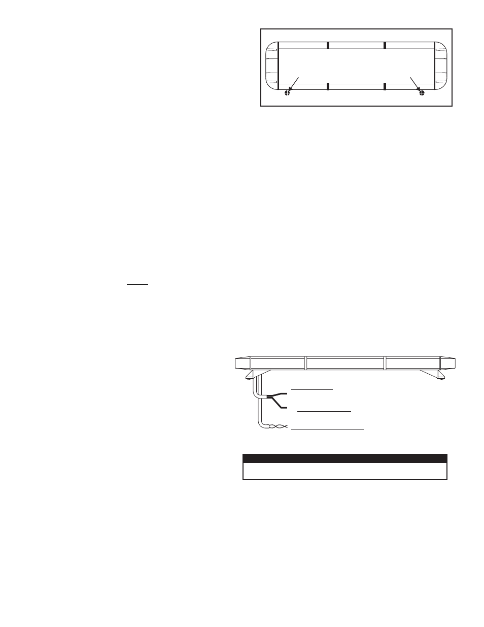
DRILLING THE CABLE ACCESS HOLE
Drill cable access hole in appropriate area
for your lightbar (see note)
FRONT OF LIGHTBAR
For
cables exiting
the Driver-side
of the extrusion
lightbars
with
For
cables exiting
the Passenger-side
of the extrusion
lightbars
with
POWER CABLE
2.
BLACK Wire
CHASSIS GROUND
2.
COMMUNICATIONS CABLE
2. GREY / CAN L
1. GREEN / CAN H
1. +12VDC / RED Wire / Requires a fuse, customer supplied.
30 AMP Fuse:
™
Freedom II
CAUTION! DO NOT LOOK DIRECTLY AT THESE LEDS WHILE THEY ARE ON.
MOMENTARY BLINDNESS AND/OR EYE DAMAGE COULD RESULT!
IMPORTANT WARNING!